Hi there,
This is a bit of a cop out of a post really because I'm going to link to another thread on another forum where another guy discribes the problem more thoroughly. Brief description though:
A particular guitar effects pedal "Digitech Whammy 4" (WH4) is used to bend the pitch of the input note up and down (various settings give a range of +2 to -6 octaves each way!). It has a rocker foot pedal to variably adjust the note (using an LDR, patterned semi-transparent film, LED sandwich to detect the angle of the pedal out of interest) and a dial (rotary encoder) to select the particular mode, and a simple PTM switch to turn it on off and a few other things. It takes a 9v AC power supply.
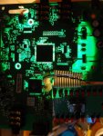
I took it appart (hoping at least a few of you will understant the need for this?).
I didn't actually change anything, all I did was probe at voltages with a multimeter, but somehow it went duff. Now the thing powers up when I attach the PSU (standard unit from digitech) but after a tiny flash from all the lights, it dies, leaving just the sensor LED on for the tredal.
The first post in this thread has a ciruit diagram attach that I cannot pick fault with. My case seems to be most similar to the very last post on the 2nd page but with similar voltage levels at the regulators to the first post on the 1st page. None of my diodes seem to have the expected 0.6v drop on them though. Some are very hot (burn your finger hot, but not combust spontaniously hot), one of the caps is quite hot, as are a couple of the regulators and (worryingly) the main CPU chip.
The question
I'm not good enough at electronics to understand that power supply system. The furthest I get is that it appears to be a clever way of getting 3 voltage levels out of one power supply. Hopefully though, some of the more developed brains on this forum will be able to scan that diagram and think "ah yes, so it works like that". Does anyone of those minds have any idea what could be the problem that keeps cropping up with these WH4 pedals?
Any help would be appriciated SO much and I can give exact details of any components in my case, eg voltage levels temperature, marking numbers (I've managed to remove the heat sinks, after the problem deceloped), however this seems to be a more broader problem with only a few common symptoms.
Did I meantion, these pedals are >£100 USED on ebay :O Hence, not wanting to just get another.
Like I say, any help = FANTASTIC
Cheers,
David.
PS, as a side note, how easy would it be to get a -9v, +3.3v and +5v power supply running from a 9v DC supply? Even possible?
Cheers
This is a bit of a cop out of a post really because I'm going to link to another thread on another forum where another guy discribes the problem more thoroughly. Brief description though:
A particular guitar effects pedal "Digitech Whammy 4" (WH4) is used to bend the pitch of the input note up and down (various settings give a range of +2 to -6 octaves each way!). It has a rocker foot pedal to variably adjust the note (using an LDR, patterned semi-transparent film, LED sandwich to detect the angle of the pedal out of interest) and a dial (rotary encoder) to select the particular mode, and a simple PTM switch to turn it on off and a few other things. It takes a 9v AC power supply.
I took it appart (hoping at least a few of you will understant the need for this?).
I didn't actually change anything, all I did was probe at voltages with a multimeter, but somehow it went duff. Now the thing powers up when I attach the PSU (standard unit from digitech) but after a tiny flash from all the lights, it dies, leaving just the sensor LED on for the tredal.
The first post in this thread has a ciruit diagram attach that I cannot pick fault with. My case seems to be most similar to the very last post on the 2nd page but with similar voltage levels at the regulators to the first post on the 1st page. None of my diodes seem to have the expected 0.6v drop on them though. Some are very hot (burn your finger hot, but not combust spontaniously hot), one of the caps is quite hot, as are a couple of the regulators and (worryingly) the main CPU chip.
The question
I'm not good enough at electronics to understand that power supply system. The furthest I get is that it appears to be a clever way of getting 3 voltage levels out of one power supply. Hopefully though, some of the more developed brains on this forum will be able to scan that diagram and think "ah yes, so it works like that". Does anyone of those minds have any idea what could be the problem that keeps cropping up with these WH4 pedals?
Any help would be appriciated SO much and I can give exact details of any components in my case, eg voltage levels temperature, marking numbers (I've managed to remove the heat sinks, after the problem deceloped), however this seems to be a more broader problem with only a few common symptoms.
Did I meantion, these pedals are >£100 USED on ebay :O Hence, not wanting to just get another.
Like I say, any help = FANTASTIC
Cheers,
David.
PS, as a side note, how easy would it be to get a -9v, +3.3v and +5v power supply running from a 9v DC supply? Even possible?
Cheers
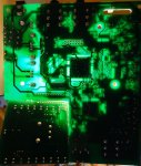
 That's the one. Connected it up, got the same light show and voltages from the other regulators. However, at the LD33v, there was only about 5V going in and something like 1.9V going out. And the regulator was quite hot, diodes were starting to heat up, and the main big chip (first one listed in post 3) was hot.