OT: Motor control circuit

laserhawk64

Senior Member
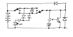
For a Picaxe-free project I'm working on, I need to control two motors, so that one is rotating opposite the other. I found a schematic on the Talking Electronics webpage (here, "Design 1" about 1/4 way down) that should work with some adaptation.

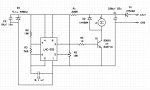
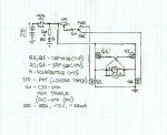
I'd like to use IRF510/IRF9510 transistors (or smaller, but they have to handle the stall current of about half an amp per motor IMO) and I want them to have a speed control. I've got a circuit diagram (attached) but I want to know three things...

(1) what value for the potentiometer (speed control)?
(2) will this work without any further changes? (if not, what does it need that it's missing?)
(3) is there a way to make this circuit even simpler, without losing functionality?


Motors here. Power is 4xAAs, so either 4.8v or 6v, depending on battery type. (Assume 6v disposables.)

FWIW, the idea is to build a simple motor-and-crank walking "robot" toy with handheld wired controller, as a kid-friendly set of instructions to (eventually) submit to Make: Magazine (obviously, credit will be given if it hits print). I'd like to think that they'd be interested in featuring something simple that a parent and child could build together in a weekend for about US$30 (at most) from a little bit of electronics and some flotsam. (To be completely kid-friendly, I want to keep soldering --and electronics-- to a minimum.)

Simple Toy Motor Controller.jpg
 

SAborn

Senior Member
Why use 2 fets if its a fixed direction for each motor, a single N-channel fet should do.
Also i think a lot of heat might be generated by using the fets in a linear mode, PWM would be a better option, but that then complicates the circuit some what.
 

SAborn

Senior Member
Why?? The PWM can originate from PICAXE, with READADC for the pot.
Yes! but the idea was not to need a picaxe in the circuit.......hence OT.
The picaxe solves so many problems, but there is times where doing things without a picaxe is also rewarding.
In doing a circuit that dont need programming a chip, keeps it a plug and play design, (or connect and solder) Truth be known most of us here learnt that way long ago.
We must remember not all electronics use micros, and its often a big first step to use a micro, but electronics is building something with limited understanding and it acctually works, that attracts an interest in electronics and then the Picaxe.
 

laserhawk64

Senior Member
@SABorn: the idea is to have it reversible as well as throttlable.

@MPep: soldering to a minimum, please, this is supposed to be a project that someone can do with their budding Pokemon trainer ;)
 

AllyCat

Senior Member
Hi,

Personally, I don't think your schematic will work (except for lighting the LED).

As you're using MOSFETs, there is no gate current, so no voltage drop across the variable resistance (potentiometer). Thus the value (and position of the potentiometer wiper) is irrelevant. Also, the gate of the "off" transistor is floating so there's no guaratee that it really will be off. Nearly all of the circuits shown in your reference use bipolars and I'm not sure that even many of those claim a "throttling" capability.

If you put resistors (perhaps a few kohms) across ALL the Gate-Source junctions and use a similar-valued pot (perhaps a little larger) then it might work. But the FETs are really intended for switching applications and the Drain current will double for less than half a volt change in the Gate voltage, so you're lilely to get a very "harsh" control. It will also be very intolerant of a falling battery voltage, not a good feature with disposables (which are intended to be used down to ideally 60% of their rated voltage).

Cheers, Alan.
 

MPep

Senior Member
LA64,

I do realise that your request was to be PICAXE-free, my comment was tongue-in-cheek. Yes it can be done, but suspect that running MOSFETs in their linear region will be wasteful in power (heat).

:)
 

laserhawk64

Senior Member
OK, can someone make suggestions as to how I might make it better? Stall current on these motors is ~0.5a per motor. I'm estimating because they have a clutch in them that kicks in before they stall, and I don't know the current at clutch kick-in.
 

laserhawk64

Senior Member
How does that work, connection-wise, and how do I control the speed? The reason for the H-bridge is that I don't see the average pot handling an amp or so of current without smoking.
 

westaust55

Moderator
A thought:
If the peak/stall current is a max of 500 mA (time to use a multimeter and test) then you could use a L293D rated up to 600 mA continuous per channel.
That would give reversing control of 2 DC motors.
 

laserhawk64

Senior Member
That works for me. I think most people who read Make: Mag ought to be able to do a little soldering... so this does qualify.

I still need an acceptable potentiometer value.
 

techElder

Well-known member
I think your whole premise is out of whack. What you drew isn't a "kids" toy. (Whether it works or not.)

And if you do find a "kid" that understands what is going on there, then they probably have already been exposed to more advanced topics (and possibly programming.)
 

premelec

Senior Member
If your circuit is as shown in post one you have a way to go to get a working circuit - it's not going to work well as shown as the pot doesn't control the motor current well etc... you might consider using a LM317T regulator hooked up as a current source and control it's current with an appropriate pot [see LM317 data sheet for current connection - basically just an R and 317]. This would also act as a stall current limiter. The current limiter would go between the power supply and the direction and drive controls. Motors will need initial higher current to start turning so ideally you'd control the voltage to the motor to determine RPM - The 317 has a voltage drop so you might need to use higher V+ voltage if you go that route...
 

SAborn

Senior Member
You could use a trusty old 555 and pwm drive the H bridge, with the pot controlling the frequency of the 555.
Its not far off using a 08m2, but it was what was common to use before we had the picaxe.

The 555 timer was yesterdays answer to the picaxe to me, and more than likely one of the first ICs many of us used back in our early days of electronics before the picaxe.

It would only seem fitting to use it again in this educational project of basic electronics, as its still a wonderful chip (Ok the picaxe is better)

Here is a schematic of a 555 circuit that i have used many times for a number of projects needing simple pwm control.

Its around 6.8Khz frequency.

The 555 needs to be the CMOS version (LMC555) as the cheaper TTL version (LM555) wont handle the frequency.

It would not be too hard to adapt the circuit for a L293D motor driver chip for your 2 motors, basically replace the transistor drive with the L293D.


555 speed controller.JPG
 
Last edited:

premelec

Senior Member
What SAborn says is good and you can put a DPDT polarity reversing switch on the motor leads to get it to run CW or CCW [or DPDT relay for single pole control]. And note that the pot is 10K... :)
 

AllyCat

Senior Member
Hi,

If you really want a simple, cheap (and rather nasty) circuit, then just use a bipolar transistor as above, with a good heatsink, and a pot (perhaps around 2k2) wiper to base, one end to the collector (or maybe the supply rail via a few hundred ohms) and the other end to ground or not connected (alternatives depend on the motor/load characteristics and the transistor gain, etc.). Reverse the motor(s) with a DPDT switch, or better still, a DPDT with a "centre off" (which potentially avoids needing a second switch).

Cheers, Alan.
 

premelec

Senior Member
What AllyCat sez is good though I'd put a emitter or drain resistor to ground [V-] for a little smoother control - perhaps 2 ohms - with a MOSFET you could use a 10K pot to the gate and put a diode or 2 between the bottom end of the pot and V- [conducting - just some voltage offset] to lessen the pot dead zone... Yo OP you still there? :)
 

laserhawk64

Senior Member
Don't worry about me, I ain't goin nowhere.

Thanks for the suggestions, everyone, I'll draw up a new schematic at some point...

EDIT: @AllyCat & premelec: transistor suggestions? Anything goes as long as it's cheap, common, and can handle the current.
 

premelec

Senior Member
@lh64 - not just current but power and heat sink likely required [might be a piece of tin can :)] - note that the power is not trivial to figure out as when the motor is at full speed most of the power goes into the motor - when half the voltage is across the transistor and half on the motor the current will be less and half the power will go into each... power = volts X amps. I'd say whatever power transistor you can get locally cheap. I have many dozens here [mostly pullouts] so don't usually look up new ones. Note that with a MOSFET there is a Vgs gate on spec which may be too high for you unless you find a LOGIC LEVEL MOSFET which would have a lower Vgs. The advantage of MOSFETS is very low gate current where bipolar you need to drive the base roughly with Ic/Hfe - however .6 amps is not a big deal... Hfe of 30 give .6/30 or 20 ma drive - which must come from the pot which drops the pot output voltage a lot when you load it and it's not at one end or the other.
Ohms law is your friend... [and you thought it was google... :) ]
 

AllyCat

Senior Member
Hi,

Sorry, I don't have any specific suggestion for a transistor type either. Basically any cheap, "audio power transistor" (with a tab) that's locally available. Perhaps with just a simple "flag" heastink, but something with more thermal intertia may help if the motor stalls.

... when half the voltage is across the transistor and half on the motor the current will be less ...
That's not necessarily entirely true (certainly not proportionally lower). If the voltage is lower then the motor is probably rotating more slowly, so less back emf is generated and the current not necessarily much lower. Like a tungsten filiament lamp, a motor might be considered more as a "constant current" load when varying the aplied voltage. But if the load (torque) on the motor increases then of course the current should rise. That's a good reason for NOT using a current source to drive a motor, because it may suddenly stall.

I've no experience of using FETs in linear applications, but suspect that this particular application is a good example of where a FET in NOT an "improvement" over bipolar. Basically the pot. is working (more) as a current source and the bipolar transistor "magnifies" its power-handling.

Connecting a pot. directly to all three terminals of a transistor (with wiper to base) is quite an interesting configuation for this application, with more "features" than a casual glance might suggest. Firstly, if the wiper is fully at the emitter end then NO current should flow in the transistor or the motor (a useful test). However, sadly you can't use this as an overall "power" switch because there is still current through the pot.

The transistor will stay OFF for about the first 10% of pot. rotation (until about 600mV VBE is reached), but for a more "refined" design, this "dead space" could be reduced by adding a small-signal diode (1N4148, etc.) in the lower end of the pot.

At the other end of the pot. travel, the base becomes connected directly to the collector so there is no risk of the base being starved of current. The transistor does not quite fully saturate, but the loss of voltage (across the load) is not likely to be significant (you'll rarely hear complaints about Darlington transistors which have exactly the same limitation).

In between these extremes there is effectively some "voltage feedback" applied (from collector to base) which potentially lowers the output impedance of the "amplifier", generally a good feature for driving motors.

Finally, if you decide to adopt the "centre off" switch idea above, then a couple of small signal diodes from one pair of poles of the switch can restore the necessary "positive" voltage to light the LED or bias the transistor.

Cheers, Alan.
 

laserhawk64

Senior Member
AllyCat, I'm having a hard time visualizing a schematic from what you wrote. Would you be so kind as to scribble one up for me? Need not be anything fancier than pencil on Post-It...
 

AllyCat

Senior Member
Hi,

Very much an untested "back of envelope" design, but it could meet your "minimalist" requirement.

All diodes might be considered "optional". The two on the left permit a single "On" LED (when using a centre-off switch), the middle diode removes some dead space on the pot track and the other two are underswing / overswing protection diodes.

Cheers, Alan.
 

Attachments

premelec

Senior Member
@lh64 - please try some stuff to see what you have and how it works... as AllyCat has mentioned a motor is an odd load - and it changes with its _ mechanical_ loading as well as RPM and voltage. I would put a small resistor between emitter and V- [1-2 ohm?] and also try running the motor and reversing switch between emitter and V- with the collector going straight to V+ 'emitter follower' configuration. [actually I'd use a MOSFET- but whatever works for your simple circuit and MOSFETs are easier to kill]. Happy fiddling!
 

laserhawk64

Senior Member
I actually don't have the parts yet -- I'd like to have the ability to plan something out and buy the parts all at once. I'm unemployed and on a fixed income, thanks primarily to the economy here, so I don't really have the luxury of playing with physical parts and potentially burning them out. It's got to be pre-planned or it doesn't fit in the budget -- and I have a rather tight budget, even at this time of year.

EDIT:

Also, my multimeter (a five year old radio shack cheapo) has kicked the bucket. A friend is giving me a replacement for Christmas, but it'll be a little while before I get it anyways.

@AllyCat: thank you! That's quite helpful.
 

premelec

Senior Member
@lh64 - OK - then it's more important to not buy stuff that doesn't work out though it will increase your junk box... even in Nowhere there are people discarding old TVs & stereos and you can mine them for parts [which is why I have piles of old parts :) ] - I've gotten motors from old dot matrix printers and vacuum cleaners etc. If you've got a dump try a visit there - I'm not sure if you've stated what your experience and abilities with electronics are -that would help. A problem with salvaged parts is they aren't easily described or duplicated if - as you say - you want to do an instructable. However since we have piles of tech junk - last years toy cars, electric toothbrushes etc. - you can usually find stuff of a sort that other people could similarly find too and thus give a lead to reuse of some of our discards - re-purposed. Do you have tools - know how to solder etc...? We all start out knowing little and pick it up as we go [or under University supervision!].
 

laserhawk64

Senior Member
The local collection center (around here you go to them, they don't come to you so much) have a simple rule about electronics: you can bring it, but once we have it, it's ours. They actually can arrest you for taking stuff -- once it's in the eWaste bin, it's technically county property. They will write down your plate and haul you off in quite inelegant chrome cuffs.

I actually asked the attendant once, that's how I know.

That said I did recently pull apart a 1984 Betamax player that's (unfortunately) about 90% ungooglable. I've not found any info on ANY of the four motors I got out of that #@!! thing... which means they probably aren't terribly useful...
 

SAborn

Senior Member
Just remember each of those 4 motors more than likely had a motor driver IC, old videos was once my source for motor driver chips, start to google some IC part numbers.
 

premelec

Senior Member
I prefer old cassette units and dot matrix printers - for DC motors - about all you get on a VCR is the door actuator :) if you have a freecycle site or advertise on craigslist you could be inundated - here you have to pay to dispose of electronic stuff 32 cents a pound - though lead & nickel batteries go to a hazardous materials place without direct charge.

How could I forget - ink jet printers! - I guess it's because I almost always get my hands into some ink at some point - but the DC drive motor is very good and usually 2 steppers... and power supply sometimes... etc...
 
Last edited:

SAborn

Senior Member
This all seems to be a project that will never get off the ground, because the intent to keep it simple is starting to effect the end result.

We use PWM for motor control for a reason, its not because it cant be done a different way, its because it works best for minimal wasted energy.
The thought of designing a circuit where +/-50% of the energy is put into heat, is just a very poor design to be putting to the public as a good educational project to learn from.

Analog still has its place in today's electronics, but IMO this is not a project for analog and digital (PWM) will far exceed an analog design for about the same expense, you quoted $30.00 well i think a 555 circuit can be done for a 10th of the cost and so simple.

Then this appears to be a thread that may never be built and just a brain storming exercise.
 

laserhawk64

Senior Member
If I can build a PWM circuit with a 555 and very few external components (ten at an absolute most), on one half of this break-apart twin perfboard, preferably with components all from the same store (web-only parts don't count!), AND can run two half-amp motors without problem, then it qualifies. Keep in mind that the two halves of that board are 15*15 on the left and 15*16 on the right (minus each corner hole) -- and the mounting holes don't match up, either! (It doesn't matter which half, though... ;) )

Also, could someone address a rather large issue that I see with PWM? The way I understand it, straight PWM to a motor turns the motor on and off rapidly (servos don't count here because they have circuitry in them that makes them do their thing). I can't imagine that being flipped on/off/on/off rapidly would do good things to any motor, especially a dirt-cheap gearmotor. I see this motor burning out very quickly from a gratuitous PWM overdose. ...or am I full of whotsit?

EDIT: also, the $30 is half gearmotors -- those things are $7 each!
 

boriz

Senior Member
The motors seem to be wire directly together, so no need for two. You can use just one with a little extra mechanism.
 

laserhawk64

Senior Member
Yeah, but it's mechanically simpler with two motors, not to mention slightly easier to build than "oh hey you gotta make a gearbox that gives two shafts and all that". Also, while each gearmotor does have two outputs, one of those outputs is for an encoder only -- it can't take a real load.
 

laserhawk64

Senior Member
Actually... that circuit's a lot simpler than I remembered. It would work... if...
(1) 6v supply instead of 12v
(2) commonly available transistor instead of BD681/BU271A (see list below)

Would also be good to double-check the passives against Radio Shark's catalog -- I don't really like supporting them, but it's better than waiting a week for Mouser ;) (for small orders, it's either break-even or cheaper, as well...) Just curious, what's a 1N5404 do?

Transistors @ Radio Crack -- MPF102 2N3055 MPS2907 2N4401 TIP42G TIP120 IRF510 MPS2222A 2N3904 TIP3055 TIP31
Also, if needed...
Diodes @ Radio Crack -- 1N4004 1N5402 1N914/1N4148 GP15M 1N4005 1N4733A 1N4003 1N4001 1N4742A 1N5404 6A05(sold as "6A 50V Rectifier Diode")

Also, Radio Carp (swap the two middle letters plz) has a mystery meat "3A Barrel Diode" 2pk -- 200A surge, 50V peak inverse, heck if I know what the crunk they are.
 

SAborn

Senior Member
The 1n5404 diode is just there in the case the power is connected to wrong way around, it can be left out if you want.

I have never used the circuit with 6 volts, but it should work, although the Zener diode will need to be changed to something live a 5V1 zener, and R4 will need to be reduced to something like 220R or 470R should do.

The BD681 is as common as sand here, and its just a 4 amp darlington transistor, surely you can find a replacement part number.

RS showed the cmos 555 listed for $1.99, i would expect it to be $0.50 else where, still 2 dollars is not a lot if its a handy store to you.
 

laserhawk64

Senior Member
Radio Shack is an electronics convenience store... they charge ridiculous prices, and the selection is wicked small, but it still (somehow) beats Mouser on small quantities -- when you factor in the shipping and wait times!

Probably best to leave the 1N5404 -- toy "robots" are fun, cooked electronics are not!

Goooooooogle suggests that a TIP120 Darlington (which is at R/S) is an acceptable sub for the BD681.

Radio Shack has a 5.1V Zener -- a 1N4733A -- listed as 1W. Is that powerful enough to fit?

Also, what wattage rating do I need on the resistors? Here's what I can get at R/S --
R1 (220R) -- 1/8W, 1/4W, 1/2W
R2 (10K) -- 1/8W, 1/4W, 1/2W
R3 (5K8) -- *not available* (substitutes? what range is acceptable here?)
R4 (470R) -- 1/8W, 1/4W, 1/2W
R5 (10K pot) -- 1/2W only (linear and audio tapers available -- please advise)

Except for R3 (and the taper for R5) everything should be clear unless I need 1W resistors for some reason!
 

laserhawk64

Senior Member
For R3, how bad would it be to put in a 5K6 resistor (as opposed to 5K8)? Radio Shack has the 5K6 in 1/2W size...

also, feedback on the questions in my previous post would be appreciated.

EDIT: one other thing. I see in the schematic, that there's a 1N4004 across the motor terminals. I assume this is to deal with spikes? Should I have that across the terminals of BOTH motors, or is only one diode needed?
 
Top