[OT] LCD contrast problem

ArnieW

Senior Member
I've been experimenting with some LCDs for picaxe from www.shopeio.com

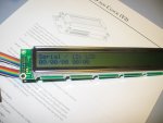
I have some 16x1 displays and some 40x2 displays.

Both appear to work ok with both the axe033 driver kit and the Peter Anderson driver kit, except that the contrast makes the displays virtually unreadable.

I have a couple of 'standard' LCDs as well that work as expected with both drivers. One came with the axe033 kit, the other with the Anderson kit. Both of these are 16x2.

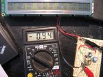
At first I thought it was just that the driving voltage was too low (ie. 4.5 volts rather than 5 volts). I have run both a 'standard' LCD and the 40x2 off the same 5 volt supply and driver. While the standard unit is clear, the 40x2 is not at all. I actually have two 40x2 LCDs and the result is the same with both of them.

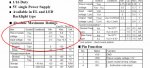
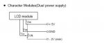
The device is a seiko L4042 with LED backlight. I have done a lot of looking around for contrast solutions to this LCD without success. The Anderson board has a fixed voltage on the contrast line, while the Rev-Ed kit has a pot to adjust. Does anyone have experience with this or ideas about how to fix the problem.

Any help would be appreciated.
 

marcos.placona

Senior Member
I was gonna say a 10k potentiometer would fix this problem for you, but apparently you've tried that too didn't you?

I've had the same problem two weeks ago, as I was trying to use a 10k resistor instead of a pot, and wasn't geting exactly the best resolution. Once I used a 10k pot and adjusted it to about half of it's resistence, the problem just fade away.
 

hippy

Ex-Staff (retired)
It's worth checking what the ideal viewing angle is of the LCD. If contrast is poor when you have it flat in front of you ( as a calculator display would be placed ) does it look much better when turned round 180 degrees and you are looking at the display upside down ?

I gave up on adding contrast pots and just wire to 0V. That's been acceptable for all the LCD's I've got.

Some LCD's actually require the Vcontrast to be taken negative. You'd need to check the LCD datasheet.
 

Andrew Cowan

Senior Member
I gave up on adding contrast pots and just wire to 0V. That's been acceptable for all the LCD's I've got.

I tried that on a white on blue backlit 4x20, and found that the background went white, so it was white text on a white background. I need to buy a pot small enough to fit on wulfden's PCB - it is frustrating haveing to change resistor values when changing the power supply.

I also had a tough time getting that LCD to work - it turned out there was a 330K resistor in my 330 ohm drawer, so the contrast was pretty much 0.

Andrew
 

Dippy

Moderator
This is merely a suggestion as I've never used those LCDs;

Check the figure for I(LC) in the Data Sheet / App Notes. For the some LCDs it is very small <1mA but for some (including that one) it seems quite a lot higher. So, maybe, you require a lower value pot, pehaps 5K or less?
I'd experiment with a couple of 1k0 or 2k2 standard res between 5V and 0V and connect the middle to Vlc.

I don't suppose you've contacted the suppliers? Just in case it's a duffer?

And, yes, I too have a drawer for each value resistor. It's called 'organisation' I believe.
 

hippy

Ex-Staff (retired)
I also had a tough time getting that LCD to work - it turned out there was a 330K resistor in my 330 ohm drawer
Had the same problem with a simple LED. Wasted hours on that. Not sure if I'd got the R's mixed up or simply took from the wrong drawer but it had me stumped. It was so obvious but I couldn't see it.
 

steska

New Member
I have three Oatley’s kits (based on P.H.Anderson’s chips) that works perfect.

The backlight intensity you adjust in software.
"?B80" being recommended.
 

Andrew Cowan

Senior Member
It is true that what may be the best contrast at one backligh level is the wrong contrast at another backlight level.

Andrew
 

Dippy

Moderator
Well, the Data Sheet I'm looking at shows terminals for LED A & K and Vlcd. I can't see any reference to software control of backlight or contrast.
Where does it say that, steska? I can't find it.
Am I looking at the wrong DS, or are you talking about a completely different LCD?

I got this horrible feeling that a tangent is approaching fast .... you'd better try and reply before a long discussion on Andrew's Backlight vs Contrast query. Andrew, contrast , like beauty, is in the eye of the beholder as well as the viewing angle. To a certain extent like Brightness and Contrast on your telly. To make a general purpose pcb for a variety of LCDs without a pot-controlled Vlcd would be silly.
 
Last edited:

ArnieW

Senior Member
This is merely a suggestion as I've never used those LCDs;

Check the figure for I(LC) in the Data Sheet / App Notes. For the some LCDs it is very small <1mA but for some (including that one) it seems quite a lot higher. So, maybe, you require a lower value pot, pehaps 5K or less?
I'd experiment with a couple of 1k0 or 2k2 standard res between 5V and 0V and connect the middle to Vlc.

I don't suppose you've contacted the suppliers? Just in case it's a duffer?

And, yes, I too have a drawer for each value resistor. It's called 'organisation' I believe.
OK, a bit closer now. Ilc is 1mA on this LCD. I tested the contrast setting with a 5k pot as suggested, but got the same result as the 10k.

The display just begins to get readable as the voltage on the contrast line reaches 0 volts. I'm guessing that this is one of those displays that needs a negative voltage here, which is a right pain.

I did some looking around and found this site where a Seiko 40x4 display is being used. This guy talks about a negative voltage and how he solved the problem:

I get my +5V from the motherboard power connector; you can also find it in the gameport or USB connector. Note that VLC (the contrast voltage) needs to be negative. I get this from the motherboard power connector's -5V (which is more like -7V on my system...). I have 920 ohms of resistance between the -5V and the VLC pin on the LCD, and that gives me good contrast.​

Are there any clever ways to do it from a single 5 volt supply, or will I need to resort to a battery below zero, or wire in another -ve rail to get it to work? I will be using it ultimately with a PC power supply so I can source a negative rail, but if there is a more elegant solution I'd be happier.

Thanks for all the help so far.
 

hippy

Ex-Staff (retired)
A battery test as you suggest should confirm if -Ve is need. An AA/AAA 1V5 with a 1K5 will limit the current to 1mA. It may need to be more -Ve.

When using a single rail supply it should be possible to generate a -Ve voltage using a charge pump driven from a PICAXE with PWM or a 555 IC. There's a Microchip Application Note ( Hints and Tips ? ) which describes a circuit to do this.

PWM can also be a good way to generate a software controlled contrast anyway.
 

Dippy

Moderator
Certainly try the battery backwards method as mentioned by hippy to test it. I haven't looked again but the Data Sheet didn't seem to suggest a 'genuine' negative voltage did it?

I take it you haven't checked with the suppliers just in case you have a duffer?

I used an ICM7660 successfully for Tosh based GLCDs which DO need 'genuine' negative. Or you could do, as suggested, a home-brew charge pump style. There are quite a lot of inverters available. Just seems odd.

I'll stick to Everbouquet and Batron :)
 
Last edited:

hippy

Ex-Staff (retired)
Finally ... found the datasheet, page 47

Vdd = 4.75V to 5.25V
Vdd-Vlc = 3V to 6.3V

So at 5V, Vlc = -1.3V to +2V

Best solution is to avoid LCD's which need negative contrast voltages ;-)
 
Last edited:

Dippy

Moderator
Well I assumed we were talking about the Seiko L4042.
The Data Sheet gives VLC of -0.3V to Vdd.
And Vdd - Vlc of 3.0 to 6.3V
All at a consumption of over 1mA. Which I think is pretty high IMNSHO.
Bit confused really, I'll pass on this one.

May I ask why you chose these LCDs? (Price??)

What happens if you do +5V --- 1k0 ---*---100R---0V and tap off at the * to Vlc?

"Best solution is to avoid LCD's which need negative contrast voltages ;-)"
- how true. But the only recent ones I've used which need negative have been GLCDs, most of which hae a built-in inverter. Yes, I know there are exceptions esp COG so save it.

Oh you've edited...
 
Last edited:

ArnieW

Senior Member
Well I assumed we were talking about the Seiko L4042.
The Data Sheet gives VLC of -0.3V to Vdd.
And Vdd - Vlc of 3.0 to 6.3V
All at a consumption of over 1mA. Which I think is pretty high IMNSHO.
Bit confused really, I'll pass on this one.

May I ask why you chose these LCDs? (Price??)
I chose this one because I wanted to display a lot of information and it seemed like a good option. The price was good too (which seemed like a bonus). So it was the one I found that promised to do the job. I was not aware of the fine print at the time - I'd not heard of negative contrast voltages being needed on some devices before.

As for checking if it is a duffer - I have two of these and they behave identically, and at the same time I ordered some 16x1s that do same. The other factor is the supplier is in the US, so not as easy to resolve that way as if I'd gone down to my local. :(
 

hippy

Ex-Staff (retired)
I've never understood specification in terms of "Vdd-Vlc", a very weird way of doing it IMO, why not just say what Vlc can be ?
 

Dippy

Moderator
hippy: "why not just say what Vlc can be ?"
- Well, it sort of does say what Vlc can be but is a bit confusing vs other specs in the same sheet (see image).


Arnie: "The other factor is the supplier is in the US, so not as easy to resolve that way as if I'd gone down to my local. "
- Don't always be driven by the wallet - it is sometimes better to let an importer take the international transit risk/costs and hence you get a more convenient warranty.
(That is merely my general opinion and I'm not talking about this instance with your LCDs but I have seen issues with cheap GLCDs bought via Ebay and, needless to say, it can be too much hassle to send them back which makes the supplier smile a lot).

IF it is standard/necessary to use negative for Vlc with these Seiko modules then some of the financial benefit has disappeared especially if you equate time with money.
Anyway, I'm sure you'll get something sorted sooner or later...
 

Attachments

rodmcm

Member
Im using two pots, one for Vo and one for AK on a 2 x 16 with Blue backlight - The AK is not always the same voltage as the the logic voltage
 

hippy

Ex-Staff (retired)
And another datasheet for the same LCD with very slightly different values but still means the same at the end of the day.
That is, Vlcd = ~0V to ~Vdd or ~5Vdc
I disagree. The highlighted "Absolute Maximums" show ...

Vdd : -0.3V to +7.0V
Vlc : Vdd-7.0V to Vdd+0.3V

Drop the range of Vdd into the Vlc equation and one gets ...

For Vdd = -0.3V : -0.3V-7.0V to -0.3V+0.3V : -7.3V to 0V
For Vdd = +7.0V : +7.0V-7.0V to 7.0V+0.3V : 0V to 7.3V

So Vlc could range from -7.3V to +7.3V but that depends on what Vdd actually is, it's a sliding window of range which varies with Vdd. With Vdd at 5V, absolute maximum is ...

Vlc : 5.0V-7.0V to 5.0V+0.3V : -2V to +5.3V

It's normal operating characteristics which are most important, absolute maximums are only there to indicate at what point chip operation is almost 'guaranteed' to disappear in a puff of smoke. The next section in the datasheet is the important one, "Electrical Characteristics" ...

Vdd : 4.75V to 5.25V
Vdd-Vlc = 3.0V to 6.0V

At 5V ...

Vdd-Vlc = 3.0V to 6.0V
Vlc = Vdd-3.0V to Vdd-6.0V
Vlc = 5.0V-3.0V to 5.0V-6.0V
Vlc = 2.0V to -1.0V

Combining Electrical Characteristics and Absolute Maximums, at 5V ...

Vlc = Below -2.0V - Expect permanent damage to chip
Vlc = -2.0V to -1.0V - May or may not work
Vlc = -1.0V to +2.0V - Correct Operation
Vlc = +2.0V to +5.3V - May or may not work
Vlc = Above +5.3V - Expect permanent damage to chip
 
Last edited:

Dippy

Moderator
And yet, under Absolute Maximum ratings from the first Data Sheet it gives VLC of "-0.3V to Vdd." which can easily confuse the issue.

If I was doing this I would arrange a battery and a 5k to 10k pot and a resistor or two so that the wiper would give -0.5 to about +3.0volts, feed the wiper into Vlc. And just see what happens. Even without any chars you should be able to twiddle between all-black and all-white.
I'm sure it would have been quicker than all those calcs :)

There comes point where you have to bite the bullet.

I see the warranty is very limited with that supplier with plenty of wriggle-outs. You would probably get no joy now even if it was duff (which is probably isn't, who knows).

How much was carriage by the way?
I only ask as an Everbouquet display from Farnell (not famous for being cheap) is £19.24 which is a lot more but contrast drive is just the usual pot. Just out of interest that's all.
 
Last edited:

ArnieW

Senior Member
How much was carriage by the way?
I only ask as an Everbouquet display from Farnell (not famous for being cheap) is £19.24 which is a lot more but contrast drive is just the usual pot. Just out of interest that's all.
Shipping was $27 USD international parcel, but I got 2x 40x2 LCDs and 4x 16x1 LCDs in that package. $71 USD for all 6 delivered in less than a week.
 

ArnieW

Senior Member
Success

Finally managed to grab some spare moments this morning to add a -1.5V rail to the LCD. It now has a single AA battery below zero and a 5k pot between +4.5 V and -1.5V. The contrast voltage ended up at -1.1 Volts for the result in the pic below.

Thanks for all the help, much appreciated.


Attachments

westaust55

Moderator
Hi Arnie,

Great to see that you got the LCD moduel working well.

Seems that although the datasheet I had indicated a single supply you needed a dual supply hooked up as per the schematic I gave in post 23.

Also good to get some feedback on how resolved. Sometimes contributors are left wondering what was the end result.
 
Last edited:

Dippy

Moderator
Well, looks like Wesaust should take the credit for single-handedly sorting out your problem then Arnie.

Arnie, one final thing before quitting this thread; as it seems that the Data Sheet is, how shall I say it nicely, confusing, it might be an ideal to measure Ilcd. IF it is milliamps then it may be worth considering an inverter style circuit or chip - purely for the convenience of single battery change operation. An ic and a couple of caps takes up less space than an AA.
 

westaust55

Moderator
Dippy,

I would hardly say that it was single handed. While I did post a scheamtic, one sheet I have indicates a single supply required and no negative required.

You gave Arnie a good lead as to how to hook up a battery.
If I was doing this I would arrange a battery and a 5k to 10k pot and a resistor or two so that the wiper would give -0.5 to about +3.0volts, feed the wiper into Vlc.
The main datasheet I have indicates ILDC typically as 1mA (with VLCD at 0.25V). But this same sheet is not the one with a schematic indicating any need for a negative suply in the schematics

This ILDC is in line with Arnies response that:
OK, a bit closer now. Ilc is 1mA on this LCD.
 

Dippy

Moderator
Haha. I was having a little joke - it was just the way it read.

(Personally, I thought those Data Sheets were sloppy in their ambiguity. That was why I suggested Arnie actually measure the current. The 'real world' values may be vastly different at the required/discovered Vlcd - who knows).
 

tiscando

Senior Member
I am very good at reading resistor codes, so i don't have to puch each value of resistor in so many little drawers like yours, instead, they are in just three seperate drawers, one is for short jump leads and up to 99r, the next is between 100r and 9k, and the last is for 10k upwards. if you're an electronics enthusiast, then you should be able to read resistor values in at least 2 second like i can. takes some practise...tip: memorise the very common resistors: 100, 470, 1k, 4.7k, 10k, 22k, 47k, 100k. note the golden or silver band is just reads the tolerance. start reading the resistor from the other side of this gold or possibly silver band. i have been doing electronics for 3 years now.
 
Last edited:

hippy

Ex-Staff (retired)
I went for one drawer for each, not least in that it removes any confusion or mistake when trying to read colours where some can often look very similar. One less thing to worry about for the sake of a few extra drawers.
 

kevrus

New Member
If done often enough, reading resistor colour codes becomes second nature and can be done without any thought, but to save searching through too many for the correct value, I use nine drawers, labelled one to nine, and segregate my resistors according to the first colour band.I follow the same idea for capacitors as well...works for me anyway
 

ArnieW

Senior Member
Arnie, one final thing before quitting this thread; as it seems that the Data Sheet is, how shall I say it nicely, confusing, it might be an ideal to measure Ilcd. IF it is milliamps then it may be worth considering an inverter style circuit or chip - purely for the convenience of single battery change operation. An ic and a couple of caps takes up less space than an AA.
An update for the sake of completion ...

I never did get around to measuring what the current is, but did buy a few 7660S chips to test out if I could run the LCD off a single supply with the 7660 supply the negative supply for the contrast (as the driver for the glcd has as an option).

I'm pleased to say that 1x7660, 2x10uF electrolytics and 1x trimpot later, it works fabulously.

Thanks to those who have guided me towards this solution.


PS. Sorry about the blur, I took the photo sans flash.
 

Attachments

westaust55

Moderator
Arnie,

Great to see that you got it all sorted out.

The 7660 is a chip I have used in the past and even recommended on this forum previously. (http://www.picaxeforum.co.uk/showthread.php?t=9448&highlight=icl7660 ) Certainly a worthwhile application to get a small negative voltage for LCD operation.

Back in the late 70’s/early 80’s I would use them in my home built computer systems to get a negative voltage from a +5 or +12V supply for more reliable RS232 operation (for printers, etc) as even in those days some equipment manufacturers only gave a positive going signal.

These days the 7660 chip is likely less used as many of the MAX232 type chips incorporate the charge-pump circuitry to give a negative voltage.
 
Top