OT: Help me calculate a Helical antenna....

Grogster

Senior Member
Hi folks.
:)

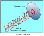
I am using a Radiometrix NTX2 434.650MHz 25mW transmitter module(driven by an 18M2 PICAXE), and the datasheet gives some examples of antennas, including a helical one made out of 0.5mm enameled copper wire, close-wound on a 3mm former.

However, this antenna is too floppy and easily bent/damaged when placing the unit in the wall - the antenna sticks up completely clear from the product, but the entire thing lives inside the wall cavity, so can brush up against bats(the insulation!), primarily during installation, and this bends the aerial out of shape. YES - I could use SMA encapsulated aerials, and will do this if there is no easy solution in the re-wind department.

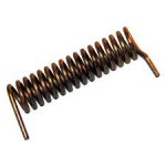
So, I want to wind another one, using THICKER wire - such as 1.25mm enameled copper winding wire - this will be thick enough that the aerial cannot be EASILY bent out of shape like the current ones can.

BUT - as all those with any RF training know, you can't just change the diameter of the wire used to wind a helical, as it is part of the equation.

So, I had a look around on the net, and there are plenty of on-line calculators to work it out for you, but they make no mention of the wire size(guage).
I will continue to search the net...

I don't suppose anyone here has any links to a calculator which would allow me to enter in the wire size to use, and IDEALLY, the number of turns, but the latter does not really matter to me, except that a helical will less turns is lower-profile. I THINK, that as the number of turns comes down at a given frequency, the diameter of the turns you are using increases in size - i think - I might be totally wrong there, but I seem to remember something like that years ago when I was reading about radio theory...
 

Grogster

Senior Member
Why are you even considering such an antenna?
Size. Helicals are normally small - where are you getting the idea they are large?
I don't doubt you - I know you know your stuff, but all the app notes etc rant and rave about how great helicals are, cos they are so small... :confused:

Anyway, have found these ones:

http://www.sunrayrf.com/product_SHOW.asp?product_id=57

Sunray do heaps of SMA aerials, so I think I will just use some of these(the fully assembled ones with SMA plug) with SMA sockets, now that I think about it, as these are pretty indestructible. ;) This is how I normally do it anyway, but was looking to save some cost on SMA sockets and aerials, if it was going to be in the wall where no-one would see it!!! :D

It was my understanding that these sealed up SMA aerials, are just the spring linked to above(or a variation of that spring depending on frequency), sealed up in a plastic tube for protection, and connected to an SMA plug for you...
 

manuka

Senior Member
I was unsure if you meant a mere spring "loading coil", or full size corkscrew helical! At 433 MHz full size means too much trouble,as the helical becomes just TOO large. Variations using stub supports rather than a self supporting heavy tubing corkscrew have arisen however - check =>http://diydrones.com/

But why are you even considering a tiny spring size? Numerous normal 433 MHz antenna are easy to make & offer great performance ( well that's if legalities are followed). What is your application & propagation terrain?
 

Attachments

Grogster

Senior Member
Application is my wireless security system I have mentioned before on these forums. Old version was external to wall. Worked fine, but aerial and box was visable. New version makes use of the lovely space inside the wall cavity, meaning there is only a standard wall-plate visable - the "Guts" are in the wall cavity(held to the wall-plate with small metal brackets, so it is all essentially one unit).

Propagation terrain - all flat.

Stuff it - I'll just use the aerials I already use, but they will just be inside the wall, so you won't see them. ;) Naturally, units will be clear of other cables and pipes, but I never had a problem with this before, even when in close proximity to mains.

Had some issues a few years back with false tripping - people here suggested the 100n across the 10k on the input, as my trips(at that time) were pull-high to trip(normally low).
The new design uses the more "Standard" and idiot-proof method of trip is pull-low(normally-high inputs via any trip switches), so that opening the circuit trips the alarm - fixes the issue with my original design too, which was bad, where if you cut the wires to the switch.......(alarm would not trip, as 5v trip signal, whereas now, circuit is cut or otherwise broken, THAT trips the alarm)
 

Grogster

Senior Member
Why not just put some heatshrink or similar coating over your existing helix to make it rigid?
It's still not rigid where it meeds the the PCB. Heatshrink WOULD stop the coils being bent out of shape though, but as the wire is only 0.5mm, it bends really easily. :(

I think if I just use the SMA's I always did, EVEN THOUGH YOU WON'T SEE THEM, they will be very strong - it should take a lot to break these. :D
I can also guarantee similar performance then too - exact same aerial arrangement. Naturally, I need to do some site-testing with the prototype.
 

g6ejd

Senior Member
Your problem is not (perhaps) having enough information on your Tx module output circuit, to then move on to determine what value of inductance (antenna) is needed to create a tuned circuit.

First off V = f .Y, where f = Freq, Y = wavelength, so in your case Y= 300/434.65 = 0.69M or 69cms long wavelength. But that's a full wave, so at resonance the voltage will be 0 at the TX end, reaching a maximum at 1/2 way then it will fall to 0 again. What does this mean, well from V/R = I (?), when voltage approaches 0, then impedance approaches 0/very low. But your Tx will have been designed for a practical 50R or so output. Now move along the waveform to get the (V/I=50) 50 R point and that generally occurs at about the 1/4 points, so for you that/s 69/4 or 17.15cms, but this is too long for most uses. So now you have to consider what the output capacitance is at 434 Mhz and derive from F0 = 1/ (2. pi. Root(L .C) the value of L = your antenna length in Henrys. This is where your calcualtor comes in, to determine what value of L is needed for resonance, now ideally get the data sheet. What your trying to do is cancel out the Capacitive reactance with your antenna/coil. So that the equation Z = R - iwC or Z = R + jwL has the 'j' bit at or close to 0 leaving just the R bit of about 50R = a match. SO that's the theory out of the way.

Now in practice, it does not really matter that much :) as your TX module will be very resilient to mis-matches. So on my calculator, I get a coil that is 4mm inside diameter, 15mm long and is 2.5 turns ~= 5.5nH assuming an output capacitance of 25pF. The inducatnce of a straight peice of wire (17.15cms) long is not a lot, about 5nH.
 

srnet

Senior Member
You could get hold of a field strength meter (DVB TV USB dongle at £6 delivered) and measure field strength as you alter dimensions\length.
 

g6ejd

Senior Member
That's a good idea, maximum field strength will generally indicate best match too, although ideally one needs to be in the far field as you get standing waves in close proximity giving nulls and highs. That said, always measure from the same place and you won't go far wrong.
 

manuka

Senior Member
You could get hold of a field strength meter (DVB TV USB dongle at £6 delivered) and measure field strength as you alter dimensions\length.
Or borrow a ~US$100 RF Explorer - this is just sort of application they thrive on. For skinflints check here for a 433 MHz approach using a $5 Dorji ASK module,with it's (undocumented) RSSI monitored by a DMM.
 

Grogster

Senior Member
Wow - I like the look of the RF explorer - I might just get one of those, it would make a nice toy to have in my toolbox. ;)
Back to reading the link...

EDIT: Yep, I think I will probably get one of these things. The ISM Combo one does 240MHz - 960MHz as well as 2GHz WiFi, so for an extra $75, I get a much more useful toy for many other frequencies such as UHF TV.(the Combo one is US$175)

ANOTHER EDIT: They also do a UHF only one, if you don't need 2GHz support - WSUB1G @ $129, but seem to be out of stock at the moment. I'd probably still get the Combo. More expensive, but 2GHz WiFi band would be very interesting to see...
 
Last edited:

manuka

Senior Member
I thought you'd like it! Thanks to a NZ agent I'm penning a SiChip review on the 240-960MHz one at present. Perhaps PM me if you fancy hands on. Stan.
 

boriz

Senior Member
If I understand correctly...

Can't you just coil thinner wire around a former? A stick? Something like that?
 

Grogster

Senior Member
You can. :)

But the issue I WAS having was that:

- Coils themselves get bent out of alignment by the bats
- Single bit of wire coming off the coil and connecting to the RF transmitter bends too, so you end up not with a helical sticking staright up, but one bent sideways, with coils out of alignment with each other.

:)

I have decided to just use the SMA sockets and SMA encapsulated aerials I always did use - strong and will not be bent out of shape, also more idiot-proof if someone not in the know takes the unit off the wall, then puts it back, not being aware of what the little coil is for. ;)
 

srnet

Senior Member
The RF Explorer is a cool bit of kit, I have been using the wide band 3G model for my many field tests on the RFM22 satellite.

I have no way of checking the absolute calibration, but ratio metrically its seems to be accurate. I did some field strength tests both near and far and then added 20db or 40db attenuators to the RF Explorer and transmitter in turn. The RF explorer indication varied by the appropriate amount give or take 0.5 to 1dB. Good enough for practical purpose.

The PC application is fairly reasonable to, for periodic signals that you might have missed, you can step back through the samples and review.

The one gripe I would have is the location of the USB connector, its on the bottom so you cant really stand it on your bench and keep an eye on the screen whilst the USB lead is connected.
 

boriz

Senior Member
The one gripe I would have is the location of the USB connector, its on the bottom so you cant really stand it on your bench and keep an eye on the screen whilst the USB lead is connected.
The magic of pressing nearby random objects into service as support :)
 

John West

Senior Member
There are two sorts of helical antennas. One is tightly wound around a former, and radiates from the side, i.e. it looks like a stick pointing straight up and radiating out to the sides. The other is a large open loop a fraction of a wavelength across, and radiates from the end, i.e. if it were standing on end like the previous example, it would be radiating straight up.

The first antenna radiates mostly in every direction out to the side. The second type forms a fairly tight beam in the direction it is pointed.
 

manuka

Senior Member
I may know (being a fellow Kiwi) but perhaps clarify that "bats" - do you mean wall interior fibre glass pink batts or electrical batteries?
 

Grogster

Senior Member
However, this antenna is too floppy and easily bent/damaged when placing the unit in the wall - the antenna sticks up completely clear from the product, but the entire thing lives inside the wall cavity, so can brush up against bats(the insulation!), primarily during installation, and this bends the aerial out of shape.
From post #1....
;)

Oh and thanks for the PM on the RF Explorer - I have made contact with the agent, and have ordered one. :)
 
Top