Oscilloscope

SilentScreamer

Senior Member
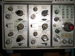
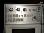
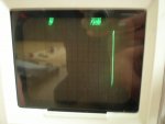
Hi, I've been given an oscilloscope but I can't seem to get it to work correctly, I have no experience what so ever with scopes so it's probably just me (I hope atleast). I've attached two pictures, one is of the scope in general and the other is a trace of a 12V AC (50Hz) signal (apologies for the reflection, I couldn't take a photo without it). Can anyone suggest what I'm doing wrong? Or is the scope broken (which is a possibility)? I think I have the correct manual here if its of any use.

I know this isn't exactly PICAXE but all the electronics I do is with PICAXE.

Thanks in advance.

EDIT: Removed the second attachment due to the better quality image in post #3.
 

Attachments

Last edited:

hippy

Ex-Staff (retired)
It could be broken. You can try connecting the scope probes to the calibration signals which are near top right below the "storage level" knob. That should give you a known reference signal.

I guess the place to start is try to get four horizontal traces with input voltages at highest settings, AC-0V-DC switches to "0V". Work your way through what does work a step at a time.

Nice scope if it does work.
 

SilentScreamer

Senior Member
Thanks hippy. I've been poking around some more with little success. I can't get the scope to "scroll" horizontally. Any suggestions for settings? There is a lot of buttons and I don't know what most do (I’ve attached two photos that are actually readable rather than those previous blurred ones).

Another idea that I've had is could it be the probes, or rather the lack of them? I've been using single core wire to make the connections but I've had a look on google and every link I find shows that they're more than just wire. If so would something like this be good enough? Or would better quality probes be needed?
 

Attachments

Last edited:

Andrew Cowan

Senior Member
Usually, higher frequencies need better probes. For teating the scope, single core wire should be fine. No signal should result in a flat line when set correctly.

A
 

SilentScreamer

Senior Member
Usually, higher frequencies need better probes. For teating the scope, single core wire should be fine. No signal should result in a flat line when set correctly.

A
I don't even get a flat line, just a stationary dot that moves vertically when the signal is changed (or two dots for an AC signal (highest point and lowest point)).
 
Last edited:

SilentScreamer

Senior Member
So there is no x travel? That means it is either disabled or broken.

A
Can you (or anyone else) have a look at the photos to see if any settings would cause it to be stationary?

Also (I forgot to mention) I have to press in the button labeled "graticule illum" (that can be seen in the second attachement of my second post #3) to see a dot at all.
 

jglenn

Senior Member
The scope is probably not in the auto mode. There are 3 modes.

1. single sweep- an ext trigger causes a sweep, horizontal axis. Just one

2. normal mode- the trigger polarity and level is set by you, select the channel, ac/dc coupling, and threshold, a knob. Scope triggers the horiz
from the signal on your CH1 or 2 vertical amp.

3. auto mode- scope will trigger sweep itself. This is what you need to test.
There should be a button that says auto/manual, it has to down probably.

Also turn up the intensity enough. You can also use the beam finder button which should make a spot in the middle of the screen.

On top of all this, if you have the x and y position controls out of whack you
can't see the trace. Then, if it is a storage mode one like my 7633, you want the non store button down, or all kinds of trippy things can happen! :confused:

AND! When you have things hooked up, sometimes the range is wrong and you can't see the trace. A trick is to put the ch1/2 vert amps switch that says:ac-gnd-dc, which is your input coupling mode, to gnd. This will force the trace to zero, wherever you put it, hopefully on the screen.
 
Last edited:

SilentScreamer

Senior Member
Thanks jglenn, I think I'm starting to get somewhere. I can control the vertical height of the scope, which should be voltage I believe. And this appears to be working fine.

So just the horizontal remains not working, I've been using the calibration signals as hippy suggested (thanks again for the suggestion, far easier to use than the transformer I was using before). The 1Khz signal should have a period of 1ms (that’s the correct term for the duration time that each wave takes?). When the time division is set to 1ms 20 full waves should be displayed? If the time division is then reduced to 50us 1 full wave is shown? On all these settings two dots are shown, one at +V and the other at 0V. Then I take the time division down to 20us and only one dot is shown.

So it appears (to me) to be reading correctly. But the dots are always in the same place horizontally about 3 quarters of the way across the screen. So it is as if the scope is jammed from sliding horizontally but not vertically and it is reading the full width but on only one point rather than the whole screen (I have no knowledge of scopes internally so it might be a misconception on my part, please excuse me if it is).

Are there any other settings that could be changed, or anything inside it that could be repaired or checked?
 

hippy

Ex-Staff (retired)
Sounds like the timebase isn't working ( oddly enough the same fault I've had with most second hand scopes I've ever got my hands on ) or not configured correctly.

There should be some "auto", free-running or non-"trigger" mode which scans the trace lines left-right regardless of what the inputs are doing.

The going to single dot at 20us timebase may be by design - not fast enough to do two at such high speeds - so don't worry about that for now, try with a slower timebase. Also if using fast timebases the lines will usually be dim so start with, say, 10ms.

Another test is to connect the calibration signal to all inputs and you should see two / four vertical bars ( or sets of paired dots ) when you adjust each channel's offset and no timebase. You can then try to find an "X-Y" setting which uses one of the channels for the left to right scan the other up-down which should turn those vertical lines into diagonals.
 

SilentScreamer

Senior Member
I've got the 4 dots (2 signals) working (I also managed 8 dots (4 signals) but the screen gets confusing). Under mode on the "main triggering amplifier" there is a button labelled auto, it is pressed down. I've also used the "single sweep" button which shows the dots for a short period of time then they go until the reset button is pressed.

The below is with one signal applied not two.
Near the mode set of buttons there is a set of buttons labelled source (image). The "triggered" light is off for all except the "LINE" setting. When the triggered light is off (at faster time bases) two dots are displayed (I fixed the one dot problem by turning up the intensity) and when the light is on the scope flashes between the two dots. Does this mean anything useful?
 

radioAK0B

New Member
sweep control

It looks like you have the sweep set to external ?

play with the sweep select switch - I can not read you pic well enough to tell what swithc setting you have

it will be call internal, just rotate the swtich control and if you hit the right position you will get horz display

Stan
 

jglenn

Senior Member
I have the same mainframe, and will describe the settings.

On the top right of the front panel, push VERT MODE left button down, this will select the left timebase module. If you only have one in the right slot, push right.

Push TRIG SOURCE left button down.

Push NON STORE down if you have that button.

On the timebase module selected, push the MODE auto button down, near the top middle. Select ac or dc coupling. Push the SOURCE int button down.

Then it should work. Not that hard once you get used to it. ;)
 

SilentScreamer

Senior Member
Thanks once again jglenn, hippy and everyone who has put their time into helping, however still no success.

I think (as hippy suggested) that the timebase module has broken. When I move the timebase module to the centre position (remove the entire unit so that it is in the middle rather than the right hand side). Then when I turn the scope back on again, with settings set so the time base isn't in use at all. I get a dot in the middle of my screen without needing to press the beam finder button (which I always needed to do to get any dot at all before). Also the dot is now in the middle of the screen rather than the far right. The dot still doesn't move however it can be moved by applying signals or adjusting the position knobs (in both the x and y axis).

Does anyone have any other suggestions as to further tests/possible solutions?
 

jglenn

Senior Member
If you have it in auto mode and it is not sweeping, it may be the trigger, play with the settings. Turn the sweep speed knob. Maybe it is broke. You can probably find a replacement module for not too much, those things are old.
 

SilentScreamer

Senior Member
If you have it in auto mode and it is not sweeping, it may be the trigger, play with the settings. Turn the sweep speed knob. Maybe it is broke. You can probably find a replacement module for not too much, those things are old.
I've tried every timebase setting. There isn't even a dot when it is selected, but when I tell it to use both voltage modules the dot appears but wont move (as I expected).

They are around £20-£30 on ebay, however they are all in the US so I'm looking at £30 postage before customs get their hands on it so I don't think its worth it, especially when I bought the entire scope for only £5, I might build womai's scope, its more than good enough for what I need.

Thanks for all the help once again.
 

hippy

Ex-Staff (retired)
I bought the entire scope for only £5
I don't recall anything I've ever bought second hand for exactly £5 ever working, but that could just be a pattern of coincidence !

If you can determine the circuit of the timebase, at least the connections from the module into the unit, you may be able to create your own replacement. It may not be perfect but perhaps better than nothing.

It's a catch 22 as well - Needing a scope to determine what's wrong with a scope :)

Note that scopes contain very high voltages and my do so even when unplugged from the mains so take care if you decide to start poking around.
 

SilentScreamer

Senior Member
I always remove the power from mains appliances, I once took apart an extension lead while the power was still connected, I didn't an electric shock but the shock when I realised was enough to never do it twice.

Well I know the calibration signals work as I can test them with my multi-meter both the frequency and the voltage are the same as the labels on the scope. Have you got any suggestions as to what to look for? I can see a lot of connections on the back of the timebase module and a lot of components inside the module I'm yet to remove the case from the main unit, there is a sticker on the back that mentions X-ray radiation shielding, is it save to remove the main case?
 

BeanieBots

Moderator
Once the 'scope has been left un-powered for 10 minutes it should be perfectly safe to remove the covers.
As a first try, with fingers crossed, simply remove the module and then put it back and try again. If luck is on your side, it might just be a simple loose plug/socket connection.
Failing that, try to get a full engineer's manual from the internet. At least you will have a circuit to work with.

It's normally the high voltage which fails on time-base modules.
With all your playing around, have you ever seen ANY movement in X direction?
Can you move the 'spot' in the X direction with any of the knobs?

If yes, then the HV section is OK and it's only the lower voltage side which has failed.
 

SilentScreamer

Senior Member
Once the 'scope has been left un-powered for 10 minutes it should be perfectly safe to remove the covers.
As a first try, with fingers crossed, simply remove the module and then put it back and try again. If luck is on your side, it might just be a simple loose plug/socket connection.
Failing that, try to get a full engineer's manual from the internet. At least you will have a circuit to work with.

It's normally the high voltage which fails on time-base modules.
With all your playing around, have you ever seen ANY movement in X direction?
Can you move the 'spot' in the X direction with any of the knobs?

If yes, then the HV section is OK and it's only the lower voltage side which has failed.
Thanks for the safty advice, I don't want a 20KV shock :eek:

I have the full manual for the scope of the internet. I can move in both x and y directions if I set the scope so it has a voltage for both axis. The posistion control of the timebase module however does nothing. I have tried all the modules in every posible combination. I will try cleaning the conections on the timebase module but they appear fine (and the voltage (if thats the correct name) modules work in the slot so the slot of the scope should be okay).
 

BeanieBots

Moderator
Once apart, check for the obvious things first. Things such as broken joints on connectors, wires fallen off, burned or charred components.
Then it's down to hard graft and experience.

Electrolytic capacitors are a common component to fail but I'd expect erratic or out-of-spec X movement rather than none with a gone cap.

With ZERO movement on X, I'd be looking for dead silicon. Without a circuit diagram it's hard to advise. If you have the diagram, check the oscillator is running. If not, fix it and try again. If it is, trace the signal to where it goes to the HV section and check to find the "missing link".

If the guts are all custom chips, put it in the bin, you'll never get a replacement. If it's mainly descretes, then you're in luck. Trace the signal as far as possible. Once it's lost, remove the suspect tranny and check it for basic function using the diode setting on a DVM. A dead tranny will be either open or short on one or more of the junctions. A good one will have a clear diode drop. Replace as/if required and check again. Repeat until working!
 

Andrew Cowan

Senior Member
If the XY mode works, you could replace the timebase with an external signal generator.

Good luck with your repairs/investigation!

A
 

SilentScreamer

Senior Member
The scopes manual is here, it’s a hefty download though at just under 50MB: http://bama.edebris.com/download/tek/7623a/Tektronix_7623A_Service_1974.pdf

I have just taken it apart (the main scope and the time base module) I can't see anything scream "I'm broken" yet so onto the multimeter. I have never seen so many components in such a, relatively, small space. I am actually shocked by it...

EDIT:
check the oscillator is running
How do I do this?
 
Last edited:

BeanieBots

Moderator
That file is a bit too big and the second link didn't work for me.
Can't you just post the circuit diagram part?

As mentioned earlier, the irony of trying to fault-find a 'scope is that it requires a 'scope.
 

boriz

Senior Member
Re: Faultfinding.

I always start with Google, using model numbers etc. Frequently someone else has had a similar problem. Failing that, I check things in order of fixing simplicity.

Start with physical stuff: Buttons, knobs, contacts, plugs, sockets, connectors, wires, dry joints etc. Anyplace dirt or movement/vibration could play a part. The old ‘impact vibration test’ can help here.

Then: Discoloured components, darkened PCB/tracks, distorted/bloated components etc.

Only after eliminating the easy stuff do I consider signal tracing or schematic analysis.
 

SilentScreamer

Senior Member
After further looking I am still yet to find anything obviously wrong. The ICs that I have found upto yet are 3 that inclue the name TEK so I assume they are custom (as it is a Tektronix scope). I have also found two labled CA3046 (datasheet). According to google they are transistor arrays with 5 internal transistors, I expect that is more use to you than me.

Which scheamtic should I post? The schematic for the timebase module or for a part of the actual scope? I have all the scope schematics but I'm still looking for the timebase module's, the main manual doesnt provide it.
 

boriz

Senior Member
Fault finding /circuit analysis / signal tracking etc is very much hands on, and very time consuming. Once you have eliminated the simple possibilities, It’s nose to the grindstone I’m afraid. It’s unlikely that anyone here can contribute much more without actually having the machine on the desk and being willing to spend several hours squinting at it. I’d be more than happy to be proved wrong (this time!).
 

BeanieBots

Moderator
Well, you've struck gold with that manual, it has everything you need.
However, as suggested by Boriz, it's now a question of hard work and methodical testing.

Besides the obvious things already suggested, your best bet is to familiarise yourself with the functional diagrams and then identify the in/out points on the relevant circuit diagrams. That should quite rapidly locate the circuit at fault. Once located, it's a question of finding the faulty device. Without datasheets for any (if used) custom devices, that is going to be the hardest part and even if/when identified, getting a replacement could be tricky.
 
Top