Using Op Amps – Differential Amplfiers
Differential amplifiers are used to amplify voltages, invert voltages and translate voltages. A typical problem might be the output of a sensor that varies from 3V to 3.2V, and this needs to be changed so it varies from 0V to 5V.
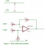
Figure 1 is the basic configuration. This has been set with a gain of 1. Any op amp will do – in this case we are using an LM324 which has 4 op amps in one package that costs 30c in quantity.
If we put 0V on both inputs then the output will be 0V. If we put 1V on the negative input and 2V on the positive input then the output is the difference, ie 2V-1V = 1V. If we put 1V on the positive input and 2V on the negative input then the output is 1V-2V = -1V.
Op amp circuits are easiest to understand when there is a + and – power supply and everything is referenced off 0V. However, positive and negative power supplies can end up being more complicated than the op amp circuit so sometimes it is easier to have a single power supply like 5V and to create a virtual earth – eg 2.5V. The maths gets a bit more complicated as everything is now referenced off 2.5V but the circuit ends up simpler.
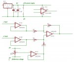
Consider the circuit in figure 2, which is a practical amplifier for many sensors. Inputs are fed through two op amps configured as voltage followers. The output is simply the same value as the input, but these op amps act to make the inputs high impedance. This is important if the sensor were say a resistor bridge with 10k resistors. If this sensor were fed directly into a differential amplifier then the amp itself would change the value of the resistor bridge.
Next we create a voltage reference around IC1C. This is simply a pot or trimpot and for starters the reference could be set at 2.5V. Again this is fed through an op amp voltage follower so the differential amplifier does not change the pot voltage.
Finally there is the differential amplifier. This has been set with a gain of 2.2, which is the ratio of 22k/10k. R1 and R3 are equal and R2 and R4 are equal. Generally R1 and R3 would not be lower than 10k but R3 and R4 can be quite high values – eg 5M for a gain of 5,000,000/10,000 or 500.
So with the circuit above, lets say we set the reference at 2.5V and put 2V on the negative input and 2.3V on the positive input. The difference is 2.3-2 = 0.3V. The gain of this amplifier is 2.2 so the output is 2.2*0.3=0.66. But the reference value is 2.5V so we need to add that to 0.66 so the actual output voltage will be 3.16V. The reference value can be shifted up and down if needed.
Now let’s go back to the original problem of a sensor that varies from 3 to 3.2V and we want to change it from 0-5V. If we add another pot between 5V and 0V we can set the wiper so it outputs 3.1V which is half way between 3 and 3.2V. Feed the 3.1V into the negative input voltage follower. Set the reference at 2.5V. The gain needs to take a 0.2V value and change it to 5V so that is a gain of 25, so the resistors will be 10k and 250k (perhaps use 220k).
The formula for output is Vref+((Vpos – Vneg)*gain).
There is a bit of a catch with many common op amps like the LM741 and 324 – the outputs can only swing to within 1.25V of the power supply rails. So an input of 4V into the voltage follower will come out at 3.75V and all the subsequent voltages will be wrong. Further, if the gain is too high then the output might not be meaningful – eg a 1V difference and a gain of 500V is not going to result 500V on the output.
There are several solutions. One can go back to the +/- power supply and make the supply volts high enough that the 1.25V doesn’t matter. +/- voltages are available from computer power supplies for instance. Or one could make the power supply 0V and 12V and at least then the output can swing between 1.25V and 5V. But it can also go to 6V or more and that might zap the input of the next chip, eg a picaxe. So then overvoltage protection with a diode and resistor would be needed.
One could do the maths very carefully so that even with a 12V supply the output never goes over 5V. This is a bit of a risky option.
Probably the best option is to use a 0V and 5V supply and use op amps that can swing rail to rail. The CA3140 is a great chip for this purpose and its pinout is shown on the diagram. The only catch is that 4 separate chips are needed compared with a single LM324.
Finally, there are low power op amps around that draw less than a milliamp, eg LP324 or a whole range of CMOS op amps.
Addit: Scroll down a few posts for a link by geforce to the maxim quad op amp with microamp current and rail to rail voltage swing.
Differential amplifiers are used to amplify voltages, invert voltages and translate voltages. A typical problem might be the output of a sensor that varies from 3V to 3.2V, and this needs to be changed so it varies from 0V to 5V.
Figure 1 is the basic configuration. This has been set with a gain of 1. Any op amp will do – in this case we are using an LM324 which has 4 op amps in one package that costs 30c in quantity.
If we put 0V on both inputs then the output will be 0V. If we put 1V on the negative input and 2V on the positive input then the output is the difference, ie 2V-1V = 1V. If we put 1V on the positive input and 2V on the negative input then the output is 1V-2V = -1V.
Op amp circuits are easiest to understand when there is a + and – power supply and everything is referenced off 0V. However, positive and negative power supplies can end up being more complicated than the op amp circuit so sometimes it is easier to have a single power supply like 5V and to create a virtual earth – eg 2.5V. The maths gets a bit more complicated as everything is now referenced off 2.5V but the circuit ends up simpler.
Consider the circuit in figure 2, which is a practical amplifier for many sensors. Inputs are fed through two op amps configured as voltage followers. The output is simply the same value as the input, but these op amps act to make the inputs high impedance. This is important if the sensor were say a resistor bridge with 10k resistors. If this sensor were fed directly into a differential amplifier then the amp itself would change the value of the resistor bridge.
Next we create a voltage reference around IC1C. This is simply a pot or trimpot and for starters the reference could be set at 2.5V. Again this is fed through an op amp voltage follower so the differential amplifier does not change the pot voltage.
Finally there is the differential amplifier. This has been set with a gain of 2.2, which is the ratio of 22k/10k. R1 and R3 are equal and R2 and R4 are equal. Generally R1 and R3 would not be lower than 10k but R3 and R4 can be quite high values – eg 5M for a gain of 5,000,000/10,000 or 500.
So with the circuit above, lets say we set the reference at 2.5V and put 2V on the negative input and 2.3V on the positive input. The difference is 2.3-2 = 0.3V. The gain of this amplifier is 2.2 so the output is 2.2*0.3=0.66. But the reference value is 2.5V so we need to add that to 0.66 so the actual output voltage will be 3.16V. The reference value can be shifted up and down if needed.
Now let’s go back to the original problem of a sensor that varies from 3 to 3.2V and we want to change it from 0-5V. If we add another pot between 5V and 0V we can set the wiper so it outputs 3.1V which is half way between 3 and 3.2V. Feed the 3.1V into the negative input voltage follower. Set the reference at 2.5V. The gain needs to take a 0.2V value and change it to 5V so that is a gain of 25, so the resistors will be 10k and 250k (perhaps use 220k).
The formula for output is Vref+((Vpos – Vneg)*gain).
There is a bit of a catch with many common op amps like the LM741 and 324 – the outputs can only swing to within 1.25V of the power supply rails. So an input of 4V into the voltage follower will come out at 3.75V and all the subsequent voltages will be wrong. Further, if the gain is too high then the output might not be meaningful – eg a 1V difference and a gain of 500V is not going to result 500V on the output.
There are several solutions. One can go back to the +/- power supply and make the supply volts high enough that the 1.25V doesn’t matter. +/- voltages are available from computer power supplies for instance. Or one could make the power supply 0V and 12V and at least then the output can swing between 1.25V and 5V. But it can also go to 6V or more and that might zap the input of the next chip, eg a picaxe. So then overvoltage protection with a diode and resistor would be needed.
One could do the maths very carefully so that even with a 12V supply the output never goes over 5V. This is a bit of a risky option.
Probably the best option is to use a 0V and 5V supply and use op amps that can swing rail to rail. The CA3140 is a great chip for this purpose and its pinout is shown on the diagram. The only catch is that 4 separate chips are needed compared with a single LM324.
Finally, there are low power op amps around that draw less than a milliamp, eg LP324 or a whole range of CMOS op amps.
Addit: Scroll down a few posts for a link by geforce to the maxim quad op amp with microamp current and rail to rail voltage swing.
Attachments
-
 53 KB Views: 380
 -
 70 KB Views: 367
Last edited: