OLED add on module causing ADC input fluctuations...any neat fixes?

Blazemaguire

Senior Member
Hi,

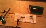
I'm just playing around with one of the fancy 4 line OLED LCD modules - at present i'm just trying to display a realtime reading from an ADC input on the display.

If I power the display from a separate power supply to the PIC (a 20x2 in this case) then the readings are stable and reliable and only vary when I move the pot (as I want). - Im generating the readings from a 10K linear pot in this case.

As soon as I wire the OLED to the same Power supply as the PIC, the readings fluctuate, by as much as + or - 10 points (on a scale of 0 - 255.) - so I can only assume the OLED updating is causing the voltage to fluctuate, and hence the readings on the ADC pin.

I've tried powering with 2AA battteries, and with a 3AA pack. - I've tried powering the PIC from a 4AAA pack with a 7805 regulator and the OLED running from the same batteries but without 5V regulation and it still happens.

Any suggestions of simple circuit fixes? - For the final product i'm developing, I really need it all off the same battery!

thanks in advance.
 

Blazemaguire

Senior Member
1000 uf electrolytic type cap? (dont have a 1000 in anything other than that at home - I'm a teacher!) - I'll try that now. - In terms of circuit what do you mean? - i'm just using a breadboarded 20x2 with the serial download circuit (10k and 22k) hooked up... oh and the 10K pot
 

Blazemaguire

Senior Member
Amazing... 1000uf electrolytic cap across the power rails seems to have done the trick!

Only on this forum can you get an answer to you problem and solve it in less than 10 minutes! - Thanks!
 

JimPerry

Senior Member
By circuit I mean a schematic (you obviously didn't just plug stuff into breadboard randomly) - Any big capacitor might do the trick - where are you? I've got a kilo of electrolytics that I got for a £fiv:eek:er ..

PS:Must replace my key baord!
 

JimPerry

Senior Member
Amazing... 1000uf electrolytic cap across the power rails seems to have done the trick!

Only on this forum can you get an answer to you problem and solve it in less than 10 minutes! - Thanks!
We aims to please - you dixed it before I replied!

Damn kebaord again!
 

Blazemaguire

Senior Member
somebody buy that man a keyboard! - I'd give you a spare one in exchange for the advice and those capacitors (i'd munch through a bag of those in school in no time) but i'm down south, in Surrey!

thanks again.
 

BeanieBots

Moderator
A lot also has to do with how the circuit is laid out.
If you just consider the 0v line for example, if you wire from the battery to the OLED then to the PICAXE you will see very large fluctuations. If you wire from the battery to the OLED and then use a seperate wire from the battery to the PICAXE you get less fluctuations. (do similar for the positive supply connections).
Wire the pot directly between the PICAXE 0v and supply.
Fit a small cap (100nF) between the PICAXE power pins as close to the PICAXE pins as possible.
Fit a larger cap (100uF should be fine but if you now have 1000uF then use that) across the OLED power pins.
Putting a cap across the battery will also help.
Do ALL of the above and you should have a rock solid reading.
 

Blazemaguire

Senior Member
All good advice. Thanks. - It's little things like this that you can't pick up from the PICAXE manuals (i guess it's too in depth for the intro guides) but you can only learn from people more experienced... or having a good electronics background (I don't.. mine is Aero Engineering!)
 

Goeytex

Senior Member
You made no mention of bypass / decoupling capacitors either for the Picaxe or for the OLED. Have you included them? You will most definitely need a 100nf across the Picaxe power pins. A bulk capacitor at the OLED supply input may also be helpful.

Consider using a "star" grounding method if possible.
 

Blazemaguire

Senior Member
star grounding? - does this mean all ground pins to one point? (i'm guessing here!) - How easy is that on a breadboard? - i'm just using the standard breadboard protocol of top row = positive, bottom row = negative. - Also, forgive my electronics ignorance, but what is a decoupling cap? - where should it go and what value? - i'd like to run off 2AA batteries in the final product.

Pic of my breadboard attached - Found the 1000uf Cap more stable than the 100uf (well both are FAR better than before (i only get + or - 1 point now... I put that down to the pot)

Please go easy on my breadboard, I know it's not the neatest... i'm experimenting!
 

Attachments

BeanieBots

Moderator
Star grounding is essentially what I described in post #8.
In your application it is also important to 'star' the supply line.
Decoupling caps are used to "decouple" the noise that each device generates from each other.
Imagine an air line with two pnumatic drills on it. One drill will draw air and starve the other. If you fit an air reservoir cyclinder near each drill they won't interfere with each other. If you fit a cap across the power line of each device then in a similar way, they won't interfere with each other. Just like the air line, it should be easy to see that exactly where the cap is placed (on the line) is just as important as how large it is.
Hope that makes it a little clearer.
 

JimPerry

Senior Member
somebody buy that man a keyboard! - I'd give you a spare one in exchange for the advice and those capacitors (i'd munch through a bag of those in school in no time) but i'm down south, in Surrey!

thanks again.
No problem - I've actually got several spare keyboards - but the beer/coffee and pipe tobacco heep gumming them up - use one to control 4 computers via a KVM.

Lucked out on the Capacitors 1Kg mixed for a fiver + £4.95 delivery - never need to buy another!

:rolleyes:
 
Top