donrecardo
Senior Member
Hi my question isnt about Picaxe but is for use
on a Picaxe based project
I am making a Voltmeter to display on an LCD
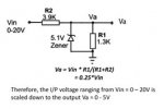
My input will be between 21v and 30v so I know I need to
use a voltage divider on the input .
I saw a small circuit for a voltage divider with the normal
2 resistors ( I was planning to use 7.5K and 1.5K to give
a max 5v from 30v input) The circuit I found also shows
a 5.1v zener across the output so if the input was more than
30v it would still give a max of 5.1v and protect the picaxes
input.
What I am hoping is that one of you knowledgeable electronic chaps
can tell me is if there is a way I could connect in an LED to show
when the zener is conducting , ie the input is more than 30v ,
and can you also confirm my choice of resistor values is suitable
I have attached the circuit I found although its values are for 20v not 30v
as I require
Regards
Don
on a Picaxe based project
I am making a Voltmeter to display on an LCD
My input will be between 21v and 30v so I know I need to
use a voltage divider on the input .
I saw a small circuit for a voltage divider with the normal
2 resistors ( I was planning to use 7.5K and 1.5K to give
a max 5v from 30v input) The circuit I found also shows
a 5.1v zener across the output so if the input was more than
30v it would still give a max of 5.1v and protect the picaxes
input.
What I am hoping is that one of you knowledgeable electronic chaps
can tell me is if there is a way I could connect in an LED to show
when the zener is conducting , ie the input is more than 30v ,
and can you also confirm my choice of resistor values is suitable
I have attached the circuit I found although its values are for 20v not 30v
as I require
Regards
Don
Attachments
-
 24.4 KB Views: 42