Non dcc sound modual for model railway

sid

Senior Member
I've had an idea for creating a non dcc sound modual for a model railway that could be built for under £20
While watching a youtube video of various locos doing their thing, I thought it would be interesting to take some sound clips of the locos and play them in relation to the track voltage on a small shunting plank that I'm in the process of making.
http://www.rmweb.co.uk/community/index.php?/topic/64767-an-asymetrical-double-outside-slip-mk2/

There would only need to be a small number of sound files that would be called upon in relation to the track voltage
eg: 0-1v engine idle
2-5v engine accelerate
5v+ full power
a decrease in voltage from a higher voltage= engine decelerating.

I searched the forum archives and came up with this interesting thread, which having read through it a few times, I think is within my ability
http://www.picaxeforum.co.uk/showthread.php?16353-mp3-playback-module
I then put together a block diagram which I think covers all the bases
Sound modual.jpg

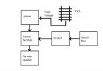
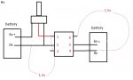
However the one thing I need some advice on, is how to convert the track voltage, which can be anywhere between 0v-14v at 1-2amps into something the picaxe can handle. I've used the readc command successfully before, however I do know that I can't put 12vdc in to one of the axes input pins.
Please could someone advise
Rgds,
Sid
 

sid

Senior Member
Thanks for that, that makes sense, but wouldn't that just put a short circuit across the rails?
 

hippy

Ex-Staff (retired)
PICAXE chips can't work below some particular voltage so you will have to have some means of storing power to use if you want a train to make a sound while there's low or no voltage.

You will also need some means to create a common 0V reference, a positive power, and positive signal for the PICAXE to read regardless of track polarity. A bridge rectifier and then a diode to the reservoir cap should allow for that; take the signal via the divider direct from "+" terminal of the bridge rectifier.
 

sid

Senior Member
I hadn't thought of track polarity, good point.
Regards no voltage, I wanted to give the picaxe its own power supply, and just wanted to be able to read the track voltage, but somehow keeping the two in isolation, if that makes sense or is even possible. but I guess the axe would need a shared ground with the track to be able to read the voltage, so perhaps a primary circuit to read the track voltage which then sends the value to another picaxe via a serial link?
 

hippy

Ex-Staff (retired)
This should allow a battery powered PICAXE to pick up the track voltage regardless of polarity. Untested, but it's what I'd start from -

Code:
       .--|>|--.--|>|--.------.
       |       |       |     .|.
)------|-------'       |     |_| 10K
       |               |      |
)------|-------.       |      }-----> ADC
       |       |       |     .|.
       }--|>|--^--|>|--'     |_| 5K
       |                      |
       `----------------------^------ 0V
Track input on the left and 0V to the PICAXE 0V, which also connects to every other 0V within that particular train. No need for isolation of supplies or multiple PICAXE chips.

Not sure how it would behave if the download lead were connected, or multiple download leads to more than one train. Probably best to remove the train from the track to program. the PICAXE.
 

sid

Senior Member
Thanks, I've got a few spare chips, so I can afford to blow a few in the learning process
I'll give this a go
Rgds
 

rossko57

Senior Member
It might be worth clarifying, the sound system is not intended to be 'onboard' and not intended to be powered from the track supply?

You did say you intended to have an independant power supply for the Picaxe (and presumably the associated audo circuits). I think you will need to make sure that is a floating supply, i.e. not earthed or commoned at all with the track supply. Else the bridge rectifier could cause unexpected short circuits to track power.

Is the train controller simply variable DC, or PWM, or variable rectified (but not smoothed) DC? All might be found in non-DCC railways, but it is likely there will be some kind of pulsing on the track. That's okay, you can just add a modest capacitor after the resistors in the bridge rectifier detector circuit.

There was an old trick in pre-chip electronics days to get true isolation; simply wire a tiny bulb across the track and use an LDR to detect the brightness. A modern equivalent would use a LED and phototransistor - these can come in one package as optoisolators of course. You would need to arrange full- or half-wave rectification (or use two LEDs) to take care of polarity reversals. You shouldn't need a high precision opto device for this.
Presumably this application doesn't actually need to know the direction.
Unlike the bulb with a built-in smoothing effect, you would I expect need to smooth or average the phototransistor output to get a "power level" analogue signal.
Going optical is more complicated but the isolation will probably be useful when multiple track sections or controllers get involved.
 

sid

Senior Member
Hi Rossko,
You make some valid and interesting points, many thanks.
To clarify some of the questions you raised..
1. This is not intended to be on-board sound, rather sound from a speaker placed on the layout.
2. The picaxe and associated sound card would be powered from its own power supply, NOT the track, Track voltage only being used as a measurement to determine which sound file to play.
I did wonder if it would be best if the picaxe and track remained isolated from each other. It was how to do this but still input the track voltage into the picaxe for it to provide a readc value that I was struggling with.
3. Track power is straight DC from a Gaugemaster controller, so I'm assuming this is un-smoothed, definitely not pwm
4. I like the trick with the light bulb and an LDR, (simple but neat) and an optoisolator is probably what I had in mind if my knowledge was better
5. Direction of loco is irrelevant so rectification will be required, or as you suggest twin leds in opposite polarity to each other.

Thanks
 

rossko57

Senior Member
Those circuits have rather different purpose - to detect a train in a track block (section). They give a yes/no indication, nothing related to power levels or train speed.

The simple bridge and isolated power will work - until it gets complicated with multiple power controllers, track sections, or sound systems (and these things do tend to multiply on model railways :)

You can always build the sound system and come back to modify the input trigger later
 

Dartmoor

Member
This is of interest as I am considering using picaxe to create sound for a model railway.
I will mention my projects, as using the picaxe for speed control may be the easiest way to read the speed?
My locos are battery powered and so far i have made 2 speed controllers using an 08m and an 18m2.
To add the sound should be straight forward, as there is already a variable with a value for speed. This is used to set PWM.
I have used infra-red and radio control to increase/decrease speed, change direction and emergency stop - but buttons on digital inputs or perhaps a potentiometer on the A-D converter could be used?
The 18m2 is capable of generating sound itself, as well as commanding samples to be played?
The picaxe board CHI035 has FET's built in and a relay can be used for reversing and the 18m2 has plenty of i/o for speed, direction and sound. The board is also designed to power the picaxe at 5v from the 12v supply (requires 7805 to be added).
Otherwise, an H-bridge can be used but this needs the PWM values inverting for reverse, unless someone knows a clever solution?
There is an interesting website - http://www.members.optusnet.com.au/satr/electronics.htm (not my work, but a very useful website!).

Hope this helps, and I will watch with interest.
 

sid

Senior Member
Those circuits have rather different purpose - to detect a train in a track block (section). They give a yes/no indication, nothing related to power levels or train speed.

The simple bridge and isolated power will work - until it gets complicated with multiple power controllers, track sections, or sound systems (and these things do tend to multiply on model railways :)

You can always build the sound system and come back to modify the input trigger later
I was more interested in the rectifier and optisolator part of the circuit rather than the rest of it
My shunting plank, has one section, one controller and one loco so nice and simple.
I'm not looking to create something to commercial standards, I just thought it would be an interesting exercise that might be able to add another dimension to the layout with costing several hundred pounds.
The isolators have now been purchased from ebay, so hopefully something for the weekend sir
 

sid

Senior Member
Untitled.jpg

I ordered some 4N35 Optoisolator/Photo/Optocouplers off ebay and they duly arrived although with no indent to let you know which is the right way round so you can find pin1. Anyway after some trial and error I came up with a circuit that sort of works, however I have some questions which I'd be grateful if someone could answer.
When the battery on the left hand side is disconnected and I put a volt meter across the terminals, I get around 6v, but when I connect the battery as shown and then put the voltmeter across pins 1 and 2 of the uncoupler with the variable resistor full on I only get around 1.5v. This voltage will increase/decrease in line with the VR being turned but only to a maximum of 1.5v.

The same thing happens on the other side, when I put the voltmeter across pins 4 and 6 the voltage moves in line with the VR but only up 1.5v.
Does this sound right?, should I be losing so much voltage?
 

rossko57

Senior Member
connect the battery as shown and then put the voltmeter across pins 1 and 2 of the uncoupler with the variable resistor full on I only get around 1.5v. This voltage will increase/decrease in line with the VR being turned but only to a maximum of 1.5v.
Yes; the little LED inside the coupler will be getting hotter and hotter as it tries to dissapate the excess power. You ought to have a current limiting resistor in series with it to prevent disaster when the potentiometer at "max" is trying to connect it directly to the battery. The 1.5V is the forward voltage drop of the diode.

You'll have to experiment a bit to find the best resistor for use with the actual train controller, maybe start with 560R and work downwards.

You can guess much the same thing is happening on the output side, with the transistor across the battery with no resistors.

This circuit looks like a useful reference
http://images.elektroda.net/72_1285622555.jpg
 
Last edited:

rossko57

Senior Member
Be aware the coupler output in that sample circuit is 'inverted', high volts = low input. That doesn't matter as you write your Picaxe code to suit - or use a subtraction to generate a 'right way up' number as its easier to think about :)

The design is intended for 5V - maybe an input resistor in the 1K area would give meaningful results from a "12V" train controller.
It will never be accurate or linear, but for this purpose you just want some variable indication of train power.

There will be a minimum input at which it will operate, 1V or so.

If you put a rectifier bridge between train controller and coupler input, it will detect either polarity - but at the expense of increasing minimum operating level because of more diode voltage drops.
This might turn out okay in practice, as I bet your basic train controller outputs "DC" which is unsmoothed and actually made up of half-wave pulses. This is of benefit for slow running. The peaks of the pulses might pass over the minimum voltage threshold before the train starts to move, that would do. Experiment!

If you do have the pulsy controller output, you will probably need to either add capacitor smoothing to the coupler output or write code to average ADC readings
 
Top