Newby problem

Hi everyone.
First of all wanna say how good this forum is and i learned alot already.
I have a project that i almost finished.
Im using Picaxe18X for it.
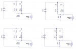
The picaxe is connected to a relay on one of the outputs also has 3 inputs(all push switches).
First input is the main one, the push switch is always on and will triger the relay when the switch is off. I have a particulat time for which the relay will stay on(0.1sec) once switch is activated. Thats the easy part.
I also need two more push switches using which i wanna be able to change time for which the relay stays on in incrisments of 0.05sec would say. This time has to be a constant. After powering the picaxe off and back on again i need for that constant to be same as it was before picaxe was turned off.
So one switch for relay, one switch for adding more time and one for decrising the time.
Please have a look at my code below (just a basic one without time adjustable switches):
Code:
 main:
           `setfreq m8
           	symbol kill=1000
          
            
label_6:	
            
            if pin0=0 then label_11
		goto label_6

label_11:	high 1
		high 0
		pause kill
		low 0
		low 1
		
label_12:	if pin0=0 then label_12
		goto main
In the above code i also have an LED which would light when relay is trigered. Im also planing of installing one or two more LEDs to indicate when "kill" time adjusting buttons are presed.
Was also wondering if possible to use time adjusting switched if pressed together to reset time to a default one of would say 0.1sec.
Thank you very much.
 
Last edited:

Andrew Cowan

Senior Member
Where 'time' is a variable

Code:
beginning of code:
read 0,time

If upswitch = 1 AND downswitch = 1 then
time = 100
endif
if upswitch = 1 AND downswitch = 0 then
time = time + 50
write 0,time
endif
if upswitch = 0 AND downswitch = 1 then
time = time - 50 MIN 0
write 0,time
endif

A
 
Last edited:
Thanks very much Andrew.
Would the time reset back to 0 every time the power is turned off?
Also do i have to assighn symbol to time like symbol time=b0 or something.
Sorry complete noob.
 
Last edited:

Andrew Cowan

Senior Member
Note I said 'read 0,time' at the beginning.

That reads the data from EEPROM (not lost when power is lost), and puts it into variable 'time'.

I later say 'write 0,time'. That writes the new data into EEPROM.

You don't have to use a name for the variable - you can keep it as b0 etc. Alternativly, you can put symbol time=b0 at the beginning, and use the word time.

Happy to help!

A
 

BeanieBots

Moderator
Andrew has made a little typo error there. "time = 0.1"
The PICAXE only supports integers so that won't work.
it should read "time = 100"

Yes, it will remember even after power has been removed.
The command "write" puts the value into EEPROM which is "non-volatile" memory.

"time = time - 50 MIN 0" won't work as expected either.
It will roll over and give a longer delay.
 
Last edited:
Andrew has made a little typo error there. "time = 0.1"
The PICAXE only supports integers so that won't work.
it should read "time = 100"

Yes, it will remember even after power has been removed.
The command "write" puts the value into EEPROM which is "non-volatile" memory.

"time = time - 50 MIN 0" won't work as expected either.
It will roll over and give a longer delay.
Why wont time - 50 MIN 0 wont work.?
What if i use smaller incrisments and decrisments?
Also i ended up having two programs in one now and its a bit tricky ... is their a way of running
Code:
main:
lable_6:               if pin0=0 then label_11
		goto label_6

label_11:	             high 1
		high 0
		pause time
		low 0
		low 1
		
label_12:        	if pin0=0 then label_12
		goto main
and

Code:
symbol time=b0
           	read 0, time

		If pin1 = 1 AND pin2 = 1 then
		time = 100
		high 1
		pause 1000
		low 1
		endif
		if pin1 = 1 AND pin2 = 0 then
		time = time + 50 MAX 200 
		write 0,time
		high 1
		pause 1000
		low 1
		endif
		if pin1 = 0 AND pin2 = 1 then
		time = time - 50 MIN 0
		write 0,time
		high 1
		pause 1000
		low 1
		endif
...together as one program or I could put a two way switch and do if switch in posiion 1 then do first program only and if switch in position two run the second program only as one of them will only be used initialy to set time correctly for the application.
Wouls that work you think?
 

Andrew Cowan

Senior Member
Just check when it is looping. This is a solution to min 0 not working.

Code:
symbol time = b0
read 0,time

main:             if pin0=0 then fire
		If pin1 = 1 AND pin2 = 1 then
				time = 100
		endif
		if pin1 = 1 AND pin2 = 0 then
				time = time + 50 MAX 200 
				write 0,time
		endif
		if pin1 = 0 AND pin2 = 1 then
				if time<50 then main
				time = time - 50
				write 0,time		
		endif
		goto main

fire:	        high 1
		high 0
		pause time
		low 0
		low 1
		
waitforpin0:        	if pin0=0 then waitforpin0
		goto main
A
Andrew im greatfull forever.
Thank you very much, now that i look at it it makes perfect sence.
Thank you again.
 

lbenson

Senior Member
Another solution to the problem with "time = time - 50 MIN 0" was given by hippy some time ago:

time = time MIN 50 - 50 ' never goes below 0
 
Another solution to the problem with "time = time - 50 MIN 0" was given by hippy some time ago:

time = time MIN 50 - 50 ' never goes below 0
Cheers, will keep that in mind.
I ran the earlyer solution by Andrew and that looks to be working very well.
Thanks for everyones input on this.
 
Note I said 'read 0,time' at the beginning.

That reads the data from EEPROM (not lost when power is lost), and puts it into variable 'time'.

I later say 'write 0,time'. That writes the new data into EEPROM.

You don't have to use a name for the variable - you can keep it as b0 etc. Alternativly, you can put symbol time=b0 at the beginning, and use the word time.

Happy to help!

A

hello again,
well ,my project is almost done now. Iwas testing it today and notesed that TIME variable in my program is reset every time i turn power off and then back on again. I think when i was testing it origianaly TIME variable was saved in the memory and was recalled afer power was turned off and then on again.
Did something happened to my PICAXE or is the program not orrect?
Thank you in advance.

Code:
` IGNITION KILL BOX V.1.0.1
symbol qs=pin2
symbol up=pin0
symbol down=pin1
symbol REDLED=0
symbol GREENLED=1
symbol RELAY1=2
symbol relay2=3
symbol time = b0
read 0,time

main:       if qs=0 then fire 		`will go to relay kill
		
		If up = 0 AND down = 0 then	 `if both switches pressed reset time to 0.1sec
		time = 100
		high redled
		high greenled 			`LED will flash 3 times
		pause 300
		low redled
		low greenled
		pause 300
		high redled
		high greenled
		pause 300
		low redled
		low greenled
		pause 300
		high redled
		high greenled
		pause 300
		low redled
		low greenled
		pause 300
		high redled 
		high greenled			
		pause 300
		low redled
		low greenled
		pause 300
		high redled
		high greenled
		pause 300
		low redled	
		low greenled	
		endif
		
		if up = 0 AND down = 1 then
				time = time +10 MAX 250 
				write 0,time
				high redled
				pause 1000
				low redled
		endif
		if up = 1 AND down = 0 then
				if time<20 then main
				time = time - 10
				write 0,time
				high greenled
				pause 1000
				low greenled	
		endif
		goto main

fire:	      high relay1
		`high relay2
		high greenled
		pause time
		low relay1
		`low relay2
		low greenled
		
waitforquickshift:if qs=0 then waitforquickshift
		goto main
 

Andrew Cowan

Senior Member
I have no idea why it doesn't work. Do note however, that the reading will be lost when a new program is downloaded - prehaps this is why it is being lost?

If you can confirm it is being lost when the power is cycles and it is not connected to a computer, then I have no idea at all... The read and write codes are all in there apart from one place:

Make sure you add a 'write 0,time' after the following:
Code:
If up = 0 AND down = 0 then	 `if both switches pressed reset time to 0.1sec
time = 100
[B]write 0,time[/B] 'ADD this!
A neater way of flashing the LEDs is:
Code:
For b1=0 to 5
high redled
high greenled
pause 300
low redled
low greenled
pause 300
next b1
This does the same thing, but looks neater and takes up less codespace.

A
 
Last edited:
I have no idea why it doesn't work. Do note however, that the reading will be lost when a new program is downloaded - prehaps this is why it is being lost?

If you can confirm it is being lost when the power is cycles and it is not connected to a computer, then I have no idea at all... The read and write codes are all in there apart from one place:

Make sure you add a 'write 0,time' after the following:
Code:
If up = 0 AND down = 0 then	 `if both switches pressed reset time to 0.1sec
time = 100
[B]write 0,time[/B] 'ADD this!
A neater way of flashing the LEDs is:
Code:
For b1=0 to 5
high redled
high greenled
pause 300
low redled
low greenled
pause 300
next b1
This does the same thing, but looks neater and takes up less codespace.

A
Thanks very much Andrew.
I just checked it gain and its working as it should... im lost as well.
Might have to go over the whole PCB with the soldering iron once more.
Thanks for the LED flash, im just starting off.
Would you know if my program will run on an PICAXE08M chip as well as on PICAXE18X? I only need 3 inputs and 3 outputs and to be able to hold TIME in memory.
Chanks you.
 

Andrew Cowan

Senior Member
PICAXE 08M:
Leg 7 = Output 0 only
Leg 6 = Input or output 1
Leg 5 = Input or output 2
Leg 4 = Input 3 only
Leg 3 = Input or output 4

So, if you want to use an 08M, you're a pin short. However, there are lots of tricks to getting around this, eg putting two switches on one input (using the ADC).

The attached picture shows that by measuring the voltage, you can work out what condition the two switches are in. The command for that is readadc.

A
 

Attachments

Last edited:
PICAXE 08M:
Leg 7 = Output 0 only
Leg 6 = Input or output 1
Leg 5 = Input or output 2
Leg 4 = Input 3 only
Leg 3 = Input or output 4

So, if you want to use an 08M, you're a pin short. However, there are lots of tricks to getting around this, eg putting two switches on one input (using the ADC).

The attached picture shows that by measuring the voltage, you can work out what condition the two switches are in. The command for that is readadc.

A
Thats excelent.
Here is image of the project i just finished. Its a bit bulky so want to make same again bit alot smaller. It has to mount on the motorbike somewhere within easy reach.
Thank you very much again, i really appriciate all the help you have giving me.


Had to modify how my relays were connected...
 
Can some one have a look to check if understand correctly READADC please:
Code:
readadc 4,b2		
		If b2 = 3 or b2 > 3 then
......

if b2 < 2 and b2 > 1 then  

........
if b2 >2 AND b2 < 3 then
is this corect going by the diagram im using for it below?


thank you
 

hippy

Ex-Staff (retired)
Your READADC will read different values depending upon which combination is set but you won't get convenient values 0, 1, 2 and 3 as you seem to be expecting.

In the top right, you jave a 10K/10K potential divider; this will deliver half of the Vbattery which will read as around 128.

Top left will read lower, around one-third of Vbattery, about 80.

Bottom left will read near zero.

Bottom right will read somewehere above half of Vbattery.
oh i see, would i be right to assume that the following will work then:
Code:
readadc 4,b2	
	
   If b2 = 130 or b2 > 130 then
......

   if b2 < 120 and b2 > 70 then  

........

   if b2 >120 AND b2 < 130 then
...as starting point and then readjust the values if not quite correct?
 

hippy

Ex-Staff (retired)
Yes, that's the gist of it.

Write a short test program which simply prints out ( see SERTXD command ) what you are reading for all four combinations and then choose values which are midway between the readings for your > and < tests.

So if you read "10, 80, 130, 200" a good choice of mid values wold be "45, 105, 165", then

if < 45
if > 45 and < 105
if > 105 and < 165
if > 165


You can tweak the R values to give a better range or spread if needs be.
Thanks very much hippy. Just tried using SERTXD and its working fab.
Cheers.
 
Top