newbie question ... best place to buy components

Noidea

New Member
Hi there,

Well here goes, this is my first attempt to join the world of micro-controllers and the greater world of robotics, a life long dream ..... so obviously I am new to all this, I seem to have grasped the basics of programming the picaxe series of chips, I understand the principal of the electronic circuits required ...

However what is the best uk website to purchase all the required bits and pieces (componentry) ... or is it more surf around until you find what you are looking for. This is what I want to avoid, One site with all your electronic needs. Oh, I dont mean the actual picaxe chips and the developers board, more the breadboards, ic's, diodes, led's and the such.

Suggestions would be appreciated.

NOIDEA
 

Dippy

Moderator
Cor.
You're going to get dozens of answers here.
It depends.

If you want good quality stuff with good technical support then try Farnell, RS Components or Rapid online.
For odd things try Mouser and DigiKey.
None of the above will be the cheapest.

I use Farnell and RS a lot. I get free next (working) day delivery 99% of the time. No quibble returns for duffers and excellent Technical support.

If you want the cheapest, and you don't worry about quality, warranty or support then try Ebay.
 

Andrew Cowan

Senior Member
Cheapest, and good for second hand items (eg transformers, motors etc): eBay
Good for low quantities (and cheap): Bitsbox
Good for speed (if local) but expensive: Maplins - also good for budget radio modules
Good for high quality radio modules: Radiometrix
Massive range but £20 minimum order: Farnell
Very cheap if you spend £50 and get free P&P (and very rapid): Rapid Electronics
Good for hard-to-get items (eg GPSs), but slow and expensive postage: Sparkfun (US)
Good for other hard to get parts, but slow (and cheapish) postage: Futurlec
Good and cheapest for PICAXEs and accessories: Rev-Ed
Odd things Farnell doesn't do: Mouser or Digi-Key (both US)

I'll edit this post if I remember any other places I've bought stuff.

A
 
Last edited:

westaust55

Moderator
source of components

Noidea,


Firstly, welcome to the PICAXE forum

As Dippy says you could get a lot of resonses here. Here are a couple of companies I use:

Jaycar have an outlet in the UK: techstore@jaycarelectronics.co.uk

I also purchase from Futurlec (www.Futurlec.com.au and www.futurlec.com )
There are different storefronts in Australia and US and they have a slightly different range of components. All components are out of a warehouse in Thailand. Very cheap, low postage costs and if they have all the parts to hand far in delivery. But I have had 2 occassions where a component is not available although their websites say in stock and they are slow to advise of delays.
 

Noidea

New Member
Thanks all

Well Thanks for the welcome and thanks for the companies. My first couple of orders are away and I am awaiting the parts.

Question, I have a bread board, pic 18x, 330r and an led, + / - power to breadboard through regulated p/s ... could someone send me a schematic for this hookup as I just cant get the damn thing to blink. I would upload a pic but have dismantled so many times I am now frustrated.

For the record I have read the manuals, I have read the forms and I am still a little lost ... my knack so far seems to be coding (thats the easy part as far as I can see/do, on the development board anyways). Its the electronics thats getting me down ... refuse to stop just need a gentle nudge in the right direction.

Thanks in advance all.

Noidea
 

westaust55

Moderator
Noidea,

PICAXE manual 1 has the circuits you need:

For the voltage regulator based power supply look at the schematic on page 24.

Even when used on a bread board (even after it is programmed) you need the pull up resistor for the reset pin and always the pull down resistor (or both for programming) to the Serial In pin. See page 29 for the schematic showing the resistors required. If not programming the PICAXE on the breadboard you could omit the 22kOhm resistor but must have the 10k pull down to pin 3

Finally see page 41 for how to connect an LED to an output pin.

Now also make sure you have a grasp of the "pin" terminology.
I am from the old school where the IC physical connections were called pins.
The PICAXE term is often "legs" or "physical pins". The term "pin" in the BASIC programming refers to logical pins 0 to 7 (out of a maximum of 8 - highest number 7) for an input or output port.
The diagrams in Manual 1 on page 8 should help you distinguish.

Hope this helps you get that LED flashing.

If still no luck, next step might be to upload a photo of your circuit and upload a copy of your program.

Edit: do you have the LED the right way around?
 
Last edited:

westaust55

Moderator
Using PEBBLE to illustrate a circuit

@Noidea,

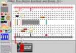
Have a look at this image of what I anticipate your breadboard should look like.

If you download the PEBBLE program, here is the circuit file to load that will give the image I have uploaded.

Code:
IC||308|270|1||U?|||PICAXE18|IC||PICAXE18_1
Transistor|BC559|209|213|1|Transistor|Q?|||1|IC|in gn out|transistor_11
Resistor|4700|292|399|1|Resistor|R?||3||IC||
Wire||288|269|21||11|#FF0000|3|11|||
Wire||288|104|21||11|#FF0000|2|11|||
Note||409|393|1||||||Reset pull up||NOTEPAD_1
Resistor|10000|265|426|1|Resistor|R?||3||IC||
Note||385|424|1||||||Ser In Pulldown||NOTEPAD_1
Wire||261|462|21||11|#000000|2|11|||
Resistor|330|534|234|1|Resistor|R?||3||IC||
LED|0|627|462|4|LED|LED?|1|||IC||led_14
Wire||638|269|21||11|#00A060|3|11|||
Wire||261|104|21||11|#FF0000|2|11|||
Wire||234|269|21||11|#000000|3|11|||
Capacitor||237|178|3|Capacitor|C?||1|4|||cap_413
Capacitor||210|147|1|Capacitor|C?||1|4|||cap_411
Note||276|209|1||||||Voltage Reg||NOTEPAD_1
Wire||288|516|21||12|#000000|3|13|||
Wire||207|269|21||11|#FF9900|3|11|||
Wire||207|462|21||12|#FF0000|5|13|||
Wire||207|597|11||22|#FF0000|1|33|||
Miscell||233|595|1||XX?||1|15|Miscell||misc_15
Wire||261|597|11||22|#000000|1|33|||
Wire||234|462|21||11|#000000|2|11|||
Wire||423|104|21||11|#FF0000|2|11|||
Wire||423|462|21||11|#000000|2|11|||
BREADBOARDSTYLE=BB10
You can find PEBBLE at a host site as given in the first post of this forum thread:
http://www.picaxeforum.co.uk/showthread.php?t=12629


A very first use of PEBBLE to show what a circuit should look like :)
 

Attachments

Last edited:

Noidea

New Member
Westaust55,

Thank you for that, this is greatly appreciated. I can now see where i have gone wrong

Noidea
 

Noidea

New Member
Westaust55,

is it okay to use a 9v battery, i am assuming (guessing really) that the voltage reg drops this down to 5v?

?Noidea?
 

westaust55

Moderator
Westaust55,

Thank you for that, this is greatly appreciated. I can now see where i have gone wrong

Noidea
1. Are you willing to elaborate where you went wrong . . . . :confused:


2. With respect to the power suppy:

your can happily operate most of the PICAXE chips from 4.5V through to 5Vdc.
Some will even operate at lower voltages (down to 3V under certian conditions) but the above mentioned range is generally best for all round use.
4.5V can come from 3 x 1.5V AA cells (eg alkaline) or 5V from 1 x 1.25 rechargable cells.

When your supply is a higher voltage than 5Vdc you need a voltage regulator such as a 7805 or 78L05 which has a 5V output.
The 7805 type need the voltage to be around 8 or more volts to operate properly. Don't go much higher as you waste energy and that wasted energy heats up the voltage regulator.
The actual regulators can handle up to approx 30Vdc input.

The low dropout voltage type regulators (eg 78L05) can operate from an input voltage closer to the output voltage.
 
Last edited:

Noidea

New Member
Hi WestAust55,

Thanks again for the help, stuck on a couple of things really (all based on your previous breadboard post);

[1] what is the value of the capacitors?
[1-a] how do i tell the neg/pos of caps (sad but true question)?
[2] where would I place the reset switch?
[3] where would I place the 3.5mm input jack?
[4] having the regulator in place means I can use any voltage between X and Y (depending on reg spec) and it will take it down to correct voltage range, correct?

what I am trying to do from your schematic is build a template that I will use forever more, consistancy and all that! I just figure if you have the building blocks of each project the same you can then problem soolve the projec and not the basics.

Your schematic and explanation has helped bring me on loads, I am actually sarting to understand a bit more. It is still a learning curve to take schematic to breadboard, as my first attempts prior to your took the whole board to achieve what you did in the first 4 lines. Live and learn.

PS. Disagree with 2B or not 2B equallling £ff, only if its a logic question, I thinks its a philosophical question and as such its probably more along the fuzzy logic lines.

<oo> NoIdea <oo>
 

BeanieBots

Moderator
Disagree with 2B or not 2B equallling £ff, only if its a logic question, I thinks its a philosophical question and as such its probably more along the fuzzy logic lines.
There are 10 types of people. Those that understand binary, and those that don't.
 

Noidea

New Member
Dippy,

The manual makes perfect sense, its transcribing it to a breadboard that has me all confused. Hence all the newbie questions, this is only my 4th week of picaxe, electronics ... ever. Oh, I changed a light bulb once does that count as electronics?:p

Noidea
 

eclectic

Moderator
Dippy,

The manual makes perfect sense, its transcribing it to a breadboard that has me all confused. Hence all the newbie questions, this is only my 4th week of picaxe, electronics ... ever. Oh, I changed a light bulb once does that count as electronics?:p

Noidea
Just a suggestion, to help get over the
conceptual leap between schematic and breadboard:

An AXE091 / a collection of Picaxe chips / some LED's and resistors

Start with something that works.

e

OR, a budget version:

AXE029
 
Last edited:

Noidea

New Member
Thanks for the suggestion of the "An AXE091 / a collection of Picaxe chips / some LED's and resistors" ... i have this and can do most things i want to ( So far :eek: ), its just getting them to the breadboard that is the issue. I have even ordered so parts from tech-supplies and taken two days off work to try and get through this barrier. I am a see it to understand it guy rather than a read it and do it type. Show me once and I never forget.

The manuals are exactly the reason I am asking, in page one WestAust55 did me a huge favor and uploaded a schematic for me, the issue is that in the manual it says there are 4 capacitors required, however the schematic only has two, I don't understand enough about electronics to know how/why.

In addition I do not yet have the knowledge to understand every nuance of electronics and hence I ask for help rather getting frustrated and giving up the whole damn thing.

(oo) NoIdea (oo)
 
Last edited:

westaust55

Moderator
Power Supplies 101

The components that you need for a power supply is somewhat dependant upon the source of power, the required voltage and the total load current.

Source of supply can include (but is not limited to):
1. batteries up to 5Vdc
2. well regulated dc output plug pack (wall wart) up to 5Vdc
3. well regulated dc output plug pack from around 8Vdc to 10Vdc
4. un regulated dc output plug pack from around 8Volts to 10Volts
5. ac output plug pack from around 8V to 10V

For 1 and 2 nothing further is required.
For 3 a voltage regulator is required to reduce the voltage to 5Vdc.
For 4, implied rectified but unfiltered/regulated so we need an electrolytic type capacitor followed by a voltage regulator
For 5, we need a rectifier (full wave is best), an electrolytic capacitor and a voltage regulator.

In each case where a voltage regulator is used, to help prevent the regulator output from oscillating, many manufacturers recommend a tantalum capacitor across the output.

Optional by me but maybe compulsory by others, is to add some ceramic capacitors also on the output and maybe the input of the voltage regulator.

With battery supplies, ff the battery capacity (in mAhr) is small and there might be relatively high load currents, it can be recommended to include an electrolytic or tantalum capacitor as a form of “buffer” to help smooth out voltage dips when there is a high load current surge.

Required Voltage –typically for a PICAXE chip and most support chips a 5V regulator is used. However some devices and modules can require other voltages such as 3Vdc. I have LCD modules out of mobile phones and humidity sensors in this latter group.

Load current can determine which specific voltage regulator chip you will require.
78L05 and LP2950-5 are 5Vdc output regulators that can supply a maximum current of 100mA. The LP series is a low drop out type which only require the input voltage to be from 50mA to ~400mV greater than the output voltage.

For higher currents the 7805 type voltage regulator is rated to supply 1 Amp. They require the input voltage to be at least 2 volts greater than the output voltage.
If the current is greater that around 300mA and/or the input voltage is more than about 8 volts then a heat sink is required as these linear voltage regulators do generate heat proportional to the current and input to output voltage difference.

At greater cost but quite compact, you can purchase switch mode voltage regulators that are very efficient and thus generate little heat so they do not need a heatsink.

It is also often recommended to add a ceramic type capacitor (100nF) across the supply for each IC in your circuit. These help to filter spikes/noise caused as the IC internal logic is switching form one state to another.

All of the above is somewhat general, however as you can see, before someone can give you an exact circuit more information would be needed. Your different projects over time may also need different circuits.
 
Top