Newbie guide to connecting servo to Picaxe 28X2

nickwoodrow

New Member
Hi guys

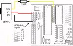
I am sure this is a simple question but I cannot find the answers anywhere on the whole internet after five hours!! I have : a Picaxe 18 tutorial board from 2002 (working). I also have the Picaxe 28 x2 I bought last week as a backup to one I purchased 10 years ago! I just about know how to code to react to switch inputs and run motors. I even sussed that I could use relays on a pin to switch a higher voltage for driving motors (probably through ignorance)! I have programmed the 28 to drive a DC motor for half a second at a time, pause and fire my camera remote. (time lapse glide rail). I am at my absolute limit of understanding but it works fine. However, I would like to use a continuous servo (which I have bought off a well know auction site) assuming it wouldn't be too difficult, so I can obtain an exact 4mm of movement of the dolly every time. I do not understand schematics (I'm left handed)! Could anybody show me a simple real life picture or photograph that shows the servo wired to either board please? I gave up on stepper motors which would probably be the bee's knees!

I have looked at the manuals. I have searched high and low! I don't mind which board I use. Please?

Thank you in advance.
 

oracacle

Senior Member
pretty simple, red goes to power, black goes to ground and the control were (normally yellow or white) goes thought a 330 ohm resistor to the pin that is going to control it.

there should be a capacitor between the red lead and the black lead.

manual 3, page 19. it wont work if you have the output from the picaxe going through any kind of driver IC.

i have only very limited experience with servos and have never had the pleasure of continuous rotation servos.

now if it was bi-polar stepper i may have been some help as i am currently working on aproject that uses one

manuales found here: http://www.picaxe.com/Getting-Started/PICAXE-Manuals/

Edit: nearly forgot, if you use 2 power sources the ground will needed to be connected together too
 

nickwoodrow

New Member
Thanks Oracle but still more questions! (if anything appears as argumentative they are not meant to be, I really appreciate your help and quick response). I am sat here with board in front of me.
So the row of output pins from 0v -0 to 7 then G (where I normally put the computer ribbon connector. pins are in pairs, small hole next to each one (can I solder from the holes)? or straight onto the pins? left or right pin or does it not matter?

black wire goes to OV )?
White or yellow wire with resistor goes to output pin 4? (trying to decyper servo code)? or pin 0?
6v supply (red) goes to ground (OV) through capacitor to servo?

Ground soldered together???

Point of discussion/Confusion: Why is Picaxe trying to flog a Servo upgrade kit that has a different chip and a bank of resistors thingy?

I would love to use a stepper motor but I think I have a few problems!!!
1. They need more than 12 volts? this makes it difficult to power in the field, unless I spend more money on a new battery and charger! (funny enough it appears that the 18 tutorial board can drive one)
2. I have know idea about the"holding torque" so not sure how it would hold my Dslr climbing up a gentle slope on the rails, and I have no access to try one out here in sunny (not) North Devon!

I truly appreciate your help and advice. Thank you.
 

oracacle

Senior Member
the capacitpr isnt vital so for ease we shall forget that for just one moment.

do you have a multi meter? if so test to see which set of pins is connected to ground, one of each pair for the output will be a ground (0V)
red goes to power. yellow white goes through a resistor to the output of your choice, check the servo comand in manual 2.

as for picaxe "flogging" servo kits, it really quite simple, most dont realise that there is a limit to the current that the IC can deliver and will connect things like LEDs, motors, relays and alike directly to the picaxe thus casuing issues. the origianl IC is most likely a darlington driver of some description which allow the direct conncetion to the board with no issue of cooking anything. the ic with the servo kit a is a bank of resistors (330ohm) that current limit while not inturpting pulsed signals which the darling driver does. servos work with a pulsed signal (from my understanding its PWM signal)

as for steppers, no they dont have to run off 12v, the one i have is rated for 44nm at 2.8 volts and 1.68amps per coil, a driver helps to improve the control that can be had from on, however the voltage reguired for 1/64 step is at least double but will giver me a 0.0003125mm resolution on a 4mm pitch ball thread

how are you driving the carriagei would think a small servo would struggle to move 2+kg, the reason i choice the motor and driver i did was to move large weight verticaly if needed, my D7100 with standard kit lense is 2.7kg.
 

nickwoodrow

New Member

eclectic

Moderator
@nickwoodrow

Welcome to the Forum.

Can you please suggest an
alternative title for your thread?

Then it can be changed,
and may be useful for others in the future.

e
 

nickwoodrow

New Member
I will be most happy to when I can get it all to work! Block Chart? Would still be glad if somebody could draw what I need on a piece of paper in real life! :) Please.
 
Last edited:

westaust55

Moderator
Exactly which board are you using with the 28 pin PICAXE?
Have you looked at the Datasheet for the board?

If it is one with a ULN2803 Darlington driver chip you cannot connect direct to the outputs of the Darlington but MUST connect direct to the PICAXE chip pins.
Rev Ed do sell a DIL resistor matrix/chip to replace the ULN2803 if you do not need the ULN2803 to drive other devices in the same project.

It is difficult to be too specific with help without knowing exactly what board etc you have.
Block diagrams or photos in the current state is what we need to see to help now - not a diagram of the finished product
 

nickwoodrow

New Member
Do you think I would be here if I didn't want to know "how to suck an egg"? I'm sure I have some good ideas and was looking for some guidance. I've worked hard trying to understand this type of stuff and came to the forum for help. I do not know anybody in my work life or locally I can ask for electronic advice. You're right, as your post suggests, I'm probably not in your league. I'll give up, clearly I'm too stupid for this forum. Hope that helps you to feel even more superior. :(
 

nickwoodrow

New Member
Thanks for your advice Westaust55. I appreciate it. I do have that chip uln2803. I do need to run one another output (Shutter operation). It is a picaxe28 https://content.solarbotics.com/products/photos/fbd095b4a565b5bbb4d168b48157c623/lrg/28510-dscn1098.jpg (fully "chipped up", not empty like the picture). which I guess is standard and I bought the motor chip because I thought I needed it. It is not in any state, it is untouched (Brand new). Perhaps I am expecting this to be easier than I thought. I don't understand "MUST connect direct to the PICAXE chip pins." What/where are the chip pins? ! Thanks anyway, sorry to be such a numskull! I would like to know, I can then make this circuit work and post some photos of the completed project board to help other newbies. Thanks again for your kind advice.
 
Last edited:

eclectic

Moderator
nickwoodrow

This really IS a friendly Forum.
People ARE trying to help.

Help us to help you please..


What have you made so far?

HOW have you connected it?

Please post a flowchart / block-chart
and a schematic (whether it's working or not)


e
 

nickwoodrow

New Member
Hi Ecletic I've made nothing! I want to make something. I want to drive a continuous servo. I haven't connected it, I don't know how. That is what I am trying to find out! I made a working prototype shown in the video with a DC motor that works well but I have a new Picaxe 28 board that I want to attach a servo. Not sure if it will be better or worse than the DC motor but I will learn something (hopefully) in the process!!

Honestly guys LOL I was just hoping somebody might have a picture of a board that had a servo connected to it! I posted this (non picaxe related) http://www.flickr.com/photos/bidefordnick/9603480276/
to help others should somebody need it (A few have faved it so it must be useful). I do try to do my bit with advice re photography in other forums when I can. I'm not just a "taker" :D
 
Last edited:

nickwoodrow

New Member
HAHA already you have helped! I now see that hours of fruitless searching Picaxe 28 is not the same as AXE020 Already I have found this....http://letsmakerobots.com/node/75 just trying to skim it now!

This helps me, Beautiful Photos, so it should help anybody. If I succeed I will share my project notes here in glorious colour! http://letsmakerobots.com/start

Thank you ecletic, the simple fact that I have been searching for the wrong "Product code/description" AXE020 rather than picaxe 28 has opened a few more doors. I have undone the noose, stopped chain smoking and eagerly await delivery of the servo (Now need to travel 20miles to Maplins to get some soldering pins)! if they have them!
Looking at circuit diagrams on their own to me, must be how it feels to be dyslexic. It is so frustrating when you want to do something but you just cannot understand.

Merry Chrimbo! (I think) :D

(Shall I send the Arduino board I've ordered back)?!
 
Last edited:

eclectic

Moderator
Reading advice from other sites
may be perfect.

However, are they "Peer - Reviewed"?
I don't know.

If I posted incorrect advice here,
I'd soon get a well deserved slap. :- (

Just my opinion, but
try and stick to this Forum.

e
 

hippy

Technical Support
Staff member
Yes, the first link. LOL! and I would like to add a continuous servo.
It would seem the easiest way to connect that servo up would be as in the circuit below. The servo would be controllable via output B.7 so "SERVO B.7, 150" etc.
 

Attachments

StigOfTheDump

Senior Member
They are not inputs. Red is 5v, Black is 0v (Page 6 of axe020 datasheet). Only the right hand top 4 of the block of 10 are inputs. Yellow is Output B.7 (page 2). The row of header pins in Hippy's drawing is not shown in the manual I have (and I don't have the board). I think these are probably a new addition as on the 18 pin project board so that you can take an output before the darlington.
 
Top