Hi All
Im making a home pinball project, and shall be running some magnets off a 08M2.
Problem is that the magnets are 4.6 Ohm load at 50 Volts, so close to 10amps drawn at 500Watts. I have tried to use transistors to drive the magnet, but the wattage is killing them... So I think i can use a mosfet to do this. problem is, I have no idea how to drive the mosfet off the 08M2. So if anyone has done similar or can suggest a circuit, that would be wonderful. I could try , but i have a bad habit of letting the Smoke Genie escape from electronic parts.
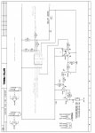
I have attached my current circuit using the transistor, but it is no good. Fine on low load, but crashes at high current.
Im making a home pinball project, and shall be running some magnets off a 08M2.
Problem is that the magnets are 4.6 Ohm load at 50 Volts, so close to 10amps drawn at 500Watts. I have tried to use transistors to drive the magnet, but the wattage is killing them... So I think i can use a mosfet to do this. problem is, I have no idea how to drive the mosfet off the 08M2. So if anyone has done similar or can suggest a circuit, that would be wonderful. I could try , but i have a bad habit of letting the Smoke Genie escape from electronic parts.
I have attached my current circuit using the transistor, but it is no good. Fine on low load, but crashes at high current.
Attachments
-
 455 KB Views: 69