Need some advice re resistors and LED's
- Thread starter reddiesel41264
- Start date
reddiesel41264
Member
We had, what was confusing me was why I would need a resistor for a 5A LED when the regulator only puts out 250ma, but now I understand ")
LED's, Mosfets, Transistors, etc are referred to not by their peak pulse current rating but rather by their
max continuous current rating.
Therefore this LED should BE referred to as "150 ma LED" rather than a 5A LED. This can be a source of confusion.
Another thing. When pulsing an LED, it CAN be pulsed (for example) at 500ma with a 250 ma supply. How ? By using a bulk capacitor
that the supply can fully charge between pulses. Get your LED working first at nominal levels, and then experiment with higher pulse currents.
reddiesel41264
Member
Thanks, I think i'll just stick to the 100-150ma mark, I don't need more than that, just wanted to clarify what I was seeing on the data sheet
Unlike many other semiconductor devices with very thin separations between die layers, or sometimes tiny wires connecting contact points, LED construction is electro-mechanically more robust. While it is possible to cause arching on the substrate with higher voltage levels, the maximum power rating of an LED is mostly dependent on how hot it gets. That's the reason a good heatsink will cause an LED to have a substantially longer useful life when being continuously run at high power levels.
High power pulses of low duty cycle will add up to a much lower average heating level than those of a higher duty cycle, so the device runs cooler. Within reason, the "instantaneous peak" power, (not the "continuous running" power an LED can be run at) is just limited to how much of a pulse shock the device can withstand, (often quite a lot) as long as the pulse duration is short enough and the duty cycle is low enough to keep the device from overheating.
But that is only useful for special purpose apps, such as communications or burning holes in things. For lighting, just stick to the average continuous current rating, and make sure the device has at least the prescribed bit of heatsinking.
@redd
After ten days and 86 posts,
just buy a few and build a couple of circuits to test.
Get some real figures on the multimeter.
Blow a couple up!
As cheap as 10p each here:
http://www.bitsbox.co.uk/optos.html
e
After ten days and 86 posts,
just buy a few and build a couple of circuits to test.
Get some real figures on the multimeter.
Blow a couple up!
As cheap as 10p each here:
http://www.bitsbox.co.uk/optos.html
e
reddiesel41264
Member
86 very useful posts that have helped me and will hopefully help others.
Also I would prefer to understand what I am doing rather than just blow things up.
Also I would prefer to understand what I am doing rather than just blow things up.
My suggestion was meant genuinely.86 very useful posts that have helped me and will hopefully help others.
Also I would prefer to understand what I am doing rather than just blow things up.
Build a couple of circuits, then test them under
real-world conditions.
For example, beam angle of the TX LED's hasn't been mentioned.
Neither has the receiver, unless I've missed something.
e
Last edited:
reddiesel41264
Member
The beam angle is 20 degrees, I'll be using it with a lense, so far I don't have any issues with that
reddiesel41264
Member
Decoupling Circuit
Hi again, Just wanted to check I have this decoupling circuit down correctly
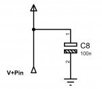
Is it as simple as that?
Hi again, Just wanted to check I have this decoupling circuit down correctly
Is it as simple as that?
Perfect as a simple decoupling circuit. 100n caps aren't usually polarised, so you don't need/want the lower bar of the symbol hatched
Some here might say that if it had another 10n (or even 1n) cap in parallel it would be even better.
Place the caps as close as physically possible to the PICAXE
...and don't forget a 100uF electrolytic from V+ to ground as a power supply reservoir/smoothing capacitor.
Get building...
Some here might say that if it had another 10n (or even 1n) cap in parallel it would be even better.
Place the caps as close as physically possible to the PICAXE
...and don't forget a 100uF electrolytic from V+ to ground as a power supply reservoir/smoothing capacitor.
Get building...
reddiesel41264
Member
Thanks