Need some advice re resistors and LED's

Andrew Cowan

Senior Member
it's best just to put a high enough value filter capacitor in place that you don't need to worry about it.
Although note that larger values of caps are usually less good at filtering high frequency noise - I usually use a combination of big and small - eg a 470uF to take out large changes, and a 100nF to remove high frequency spikes.
 

Dippy

Moderator
"I'm sure Dippy can answer for himself,..."
- yes, I have been known to do that. :)


Amongst my irony and when I'm not joshing (Splutter!) I try and post to get people thinking rather than serve up on a plate.

One of the things I've been waiting for are comments on component selection.
It never happens.
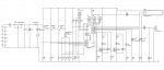
You , quite rightly, suggested a logic level MOSFET. Yup, far better.
We all tend to use similar components for no better reason than someone has used one before - sometimes it's a perfectly good reason too , so I'm not knocking it.
But, when significant , we also have to look at other component specs.
Again I say 'when/where significant'.
In this circuit a lower rated MOSFET may perform better. Especially at higher frequencies.
Why?

Note: I DO appreciate that cost and availability play a part, but when you want the best you may have to hunt.

PS. In any circuit. esp noisy ones, put a capacitor or two on your PIC power pins to act as decouple/bypass.
And I would be tempted to put a small gate resistor in too for a bit of PIC protection potential.
 
Thanks Dippy. I haven't done any more work on my circuit since I last posted (been to busy with work) but will hopefully do a bit more this evening and post an update
 
IR WIP.jpg

So here's the stage I'm at, it's a bit of a mess at the moment visually but it's not finished yet. Do you know if it is possible to utilise the hidden power pins in picaxe VSM?

Edit: I just realised I've connected C5 up to the LCD, that should actually go straight to ground
 

Goeytex

Senior Member
IRL520 is an older design with relatively high RDSon and mediocre performance by today's
standards. There are much better choices nowadays. Look for a Logic Level MOsfet with
a lower RDSon and lower total gate charge.

(Maybe Rev Ed could update manuals to reflect a more modern FET)

Same with 7805 Regulator ...Old technology. Consider a Low Drop Out (LDO) regulator instead for
decreased heat and longer battery life.

The time is coming when we will have to consider using SMD components in our projects as many
through hole parts are disappearing at a rapid rate. Using SMD give thousands of more choices in
component selection.
 
Last edited:

Dippy

Moderator
Well said Sir!

And MOSFET selection can be critical.... remember, generally the fatter the MOSFET the fatter the total charge/capacitance.
So, like I was trying to hint at in my previous post, selecting an OTT device can (in many cases) compromise the performance.
I know it's easy for me to say , but try and understand the mechanism - it really can help.
You don't have to go mad with the majorities and minorities but a general idea will really aid design and selection.


PS. I would suggest that you include a ceramic //d with an electro cap on the PICAXE power pins. I know I keep on and on saying it and most people ignore me, but it really can help especially on circuits where you have transients (pulses/noise) kicking around.
 

Dippy

Moderator
Very pretty devices.

How did you make your choices?

Did you do any measurements or calcs when sourcing the regulator?
What's your worst case current going to be?
Do you realise that you can power the LEDs from a second regulator or straight from the batts?

The MOSFET.
What kind of frequency will you be switching? I've forgotten.
It may not be important in your circuit but you don't seem to have understood the previous comments about charge and capacitance. I would use a much lower rated MOSFET as mentioned previously , but I've never used MOSFEts before.

I always like to do ballpark calculations to determine a range of parameters and then go to the inventories of big places like Farnell , RS and Digikey and see what fits the bill.


Otherwise, just buy a few different types and get on and have a go as it sounds like it'll be quicker. :)
Good luck with the project. Did I mention decoupling/bypassing for the PICAXE?
 
I made my choices by looking at the datasheets for the current components and then looking at the datasheets for other components and I chose the ones that had the most desirable qualities based on what you guys had said - such as LDO and RDS on.

As far as powering the LED's straight from the batteries, how would I switch them on via the IC? surely I'd still need a transistor of some kind?

The signals I'll be sending will be 38Hz

Ah yes, I forgot to check out charge and capacitance, I only looked for the other two things I mentioned.
 

Dippy

Moderator
Just looking at Rds on can be way off the mark. Other parameters are just as important.


If your driver is weedy (and the PIC output is relatively weedy) then you need to have a low total charge/capacitance.
This will result in faster switching AND less load on the poor old PIC semi.
Charge/Capacitance is proportional to current rating in MOSFET , hence my previous comment about lower ratings - I was hoping a light would come on ... and so are you (haha) , in this case an LED.

Your LED current is piddly in the MOSFET world so you can select a much lower rated MOSFET with a much lower total charge.
Do you understand the importance of all this? (don't worry if you don't , most people forget about it. I've seen 10 threads recently where no-one has even considered it.)

When you have a low-sided switch like this , the 'power supply' to that IR + res + MOSFET circuit element could come from another source. That could be a second regulator or directly from the batts. With the latter you would have to recalc your resistor values of course and note that the IR o/p power would vary with batt strength. For something like an average remote control it wouldn't matter a jot.
The BIG advantage of direct-from-Batts or from second regulator is that it removes 99% of transient issues for the PIC compared to a single shared regulator. Having said that, a bit of careful electronic and physical design can get rid of that.

It might not be significant in your case , I mentioned at food for thought.


Regulator? Current? No mention , so I hope you've specced it OK.

I like spending other people's money; get a handful of bits, try it out and look at it with a 'scope.
With IR modulated comms a sharp driving current may not be significant anyway....
 
Yes, that makes sense, I shall have another look at mosfets and see what I can find. I shall also have another look at the regulator and I may do as you suggest and use a second one.
 

Dippy

Moderator
There are dozens suitable.
Look through Farnell, RS etc.
I'm afraid you may have to consider surface mount. No big deal, but remember not to mirror footprint if mixing S/m with Th/Ho. SOT-23 easy even for a shaky hand.
Here's an example. 12p +VAT. Is that OK? :)
http://uk.farnell.com/international-rectifier/irlml2060trpbf/mosfet-n-ch-60v-1-2a-sot-23/dp/1791578

There are so many options but surface mount ones are better specced - I'm afraid manufacturers make them for manuafacturers and not for hobbyists. You may find a nice through hole device.
Keep searching. Good luck.
 
Thanks, that looks good, I think I'll have to get an adapter board so I'll do a bit more searching and see if I can find a through hole one.

On the subject of decoupling the power pin, what value capacitor should I use? I can't actually find a data sheet for the axe28x1 chip with the relevant info on it.

And does anyone know how I actually make use of the power pins in Picaxe VMS?

Thank you :)
 

Goeytex

Senior Member
An adjustable second regulator for the LED could eliminate the need for a current limit resistor and improve efficiency somewhat.

For example, if the max forward voltage of the LED is 1.7v then set the second regulator to that voltage. If you want to overdrive the LED a bit, then a slightly higher voltage could be selected.

For extra range/coverage you could put 2 led's in series & set the voltage to 3.4v. In this case a fixed 3.3v LDO
might be ideal as the difference in output from 3.3v vs 3.4 volts will be negligible.

A 400 ma adjustable LDO might be a good choice. Be sure to use a large bulk capacitor
at the regulator output. 100uf should do ok.
 
Last edited:

MartinM57

Moderator
I would probably use neither ;) Why? Because it's not clear from the data sheet what their behaviour is with a Vgs of 5V and they just look way over the top for switching 100mA or so through a IR LED.

How I would search:
- uk.farnell.com - other suppliers are available
- search for "logic mosfet" - as that is what you really want
- select the parametric "Transistor Polarity" as "N channel" - as that is what you need
- select the parametric "Rds(on) Test Voltage Vgs" of 4.5v or 5v - as that will find MOSFETs that work well when driven by (just) 5volts Vgs
- sort by price ascending - why spend more than you need

...and browse.

The 2n7000 is a general purpose, cheap, small, easily handled, logic MOSFET - but uh-oh, it says Rds typically 2 ohms, max 5.3 ohms at VGS = 4.5 V, ID = 0.5A, so it must be rubbish compared with all these 0.06 ohm MOSFETs in big TO220 slabs that you bolt to heatsinks to keep them cool. Hmm - but you've already got a 25R resistor in your load line, so why not reduce it to 20R and use a 2n7000? Quick double-check calc ... if it is 5 ohm Rds then at 100mA Ids (or whatever you're number is), then power dissipated = I^2 x R = 0.1 X 0.1 x 5 = 0.05W, so it's not going to get hot either.

I wouldn't look any further to be honest...the situation would be different if you were trying to switch an Ids of 10A at 10Khz with a PICAXE output - but you're not :)
 
Last edited:
Thanks, I was getting focused on going for lower RDS on while trying also to find a through hole mounting. I shall go with your suggestion, it makes my life much simpler :D
 

Goeytex

Senior Member
I did a quick parametric search at Farnell and found a pertty good MOSFET candidate for you.
A parametric search can save you a bunch of time reading through datasheets & sourcing parts.

MFG # PMV117EN
Farnell # 758115

RDs ON .............. 117 milliohms
Total gate Charge ... 4.6 nC
Input Capacitance ... 147pf
Gate Threshold ...... 2.0v
VDS ................. 30v
Continuous Current .. 2.5 amps

Cost ........ £0.166 ea
In Stock .... 2,476

Much better than the 2n7000
 

MartinM57

Moderator
Yep, that seems a good one. Nice find. Bit small though. Didn't come up on my search as I initially looked at "LOGIC MOSFET"

It's not "much better that a 2n7000" if you want a through hole component :D

EDIT:...and it's got a nice friendly data sheet with an explicit graph of Ids vs Vgs undr what looks like static currents, whereas most other MOSFET data sheets only show this graph under pulsed conditions. I'll add it to my grimoire...
 
Last edited:
Thanks again, as this is only a hobby if it wont make a huge difference I rather go for convenience, and I'd prefer through hole rather than having to use an adapter board
 

Goeytex

Senior Member
That would be incorrect. The "PEAK" current rating is 5 amps and is based upon pulse width of 25us, a duty cycle of 1.25 percent and a temperature of 25C. It must then be derated as duty cycle and temperature increases.
 

erco

Senior Member
Whoa, partner. That LED is rated at just 150 mA max, so you'll probably want to run it at 1000 mA or less. You'll need a resistor for sure. Ohm's law, voltage drop and all that jazz.

And your regulator is only rated at 250 mA. My guess is that you're starting out in electronics and you'll probably blow the regulator somewhere along the line. If I were you, I'd start with a bulletproof LM7805 until I got REAL familiar with Ohm's law.

Seriously, everyone makes mistakes as they learn, so it makes sense to use cheap overspec'ed parts!
 
In that data sheet it says under pulse conditions 1.5 amps and can be used up to 5 amps. So what is this extra 3.5 amps? and why cant I make use of it? :)

Also on the heat side of things, the LED's power dissipation is 1.11W, so do I need a heatsink for this? or is that dissipation only applicable with the use of a heatsink?

Thanks :)
 

Goeytex

Senior Member
The regulator only puts out 250ma though, but you're saying i'd still need a resistor?
Yep.

How do you propose to do this where regulator only supplies 250ma while the LED is trying to pull 5 amps ? Stuffs gonna get hot or blow up.

Instead of trying to do hat tricks with this LED why not just operate it normally at 150 - 200 ma and see if it does the job. If it doesn't then experiment from there. You might want to buy a hand full of these so you can keep experimenting as you blow them up trying to operate them beyond their limits.
 

Goeytex

Senior Member
Also on the heat side of things, the LED's power dissipation is 1.11W, so do I need a heatsink for this? or is that dissipation only applicable with the use of a heatsink?
It's important to read the entire datasheet including the footnotes. The notes say 1.1w when the LED is immersed in a liquid silicon bath that represents an infinite heat sink. This is theoretical only and is used as a reference for derating based upon the thermal characteristics of a given heat sink.
 
Oh I see what you mean now, I was thinking if only 250ma comes out of the regulator then that is the max that can go to the LED but I realise that it's the LED that will be pulling the current and trying to get more than whats available. So if I limit the 250ma to 100-150 via a resistor it should work fine? And no heatsink required?
 
So I did a quick calculation to work out what resistor I would need, 150ma is the desired current, 5v source, 4v forward voltage of the LED. The result was I would need a 6.666666* R resistor, does this sound right? or have I missed something in my calculation? Also how does that calculation account for the 250ma from the source?

I figured that if this is the correct calculation I should use something like a 12R resistor, how does that sound?

Thanks once more!
 

boriz

Senior Member
Built a little LED strobe, ages ago. Used one 5mm white LED (I think it was 20 or 40ma MAX) powered directly through a transistor from a PP3. In theory, when the transistor was fully on, there would be at least a couple of amps through the LED.

To drive the transistor, I used two 555s, one for the frequency (period), one for the pulse duration (duty). Each adjustable with a pot. I switch it on with the duty set to zero and slowly adjusted it until the LED showed roughly the same brightness as it does when driven (continuously) with the recommended current.

Had fun with it, until I got the duty too high and blew the LED.

Many factors were limiting the Max current, like the internal resistance of the battery, the capacitance of the LED etc. but the point is, large currents can be used so long as you keep the duty low enough.
 

Goeytex

Senior Member
I came up with 11 ohms but I cheated using SPICE. Remember we already have about 2 ohms in the 2N7000 FET.
You should be ok with anything from 8 - 10 ohms considering the pulse widths and average duty cycle of the
modulated 38Khz Signal.
 
Top