I think I can eventually bodge my way to a solution to this, but if possible I'd like to do a proper job of optimising this on paper first. Only trouble is, my maths isn't up to it...
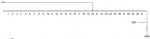
Have a look at the attached jpeg. The circuit is very simple; a version of it with all 10K pots has been tested, and it works very well, but the spacing between output values is far from linear, obviously.
If sourcing the correct value resistors was not a problem, how would I calculate what resistor values to use to get even spacing between each adc value? (1-31.) Outputs in an ideal world would be 8, 16... 240, 248.
There is probably an optimum value for the total resistance of the resistor 'array', from the picaxe's point of view, and obviously the value of the resistor between adc and ground will affect the overall spread of adc values that would be seen.
How should I go about this? The circuit design has to be as shown, btw. I'm aware there are better ways to do this, but they don't work for my application.
Attachments
-
 51.1 KB Views: 38