Need help with "Motorized macro rail on the cheap" macrophotography project

fjwallace

New Member
Hi,
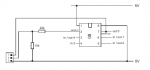
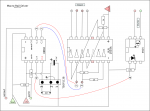
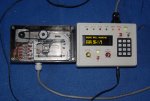
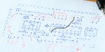
I'm a HS science teacher and wanted to use this with my students. I made a 'manual' version and it works great but we hate having to flick switches hundreds of times and so I made this automatic version I found on the web (link below) over the holiday break. Unfortunately, the software that was written for this was for the 08M and I had to buy the 082M which includes a different programming editor (which means some of the commands don't work - infrain2 for example) and the chip apparently has a different configuration compared to the 08M even though the Picaxe website states they are compatible (a program error stated that pin 2 was 'output only' whereas it was used as an input for in the original code (at least in my quick look through the program)). I was hoping someone here had built this project with the same chip (082M) and had re-written the code and would be willing to help me out or anyone with some 082M programming experience could help. I have never used Picaxe before and picked this project because it looked like everything was 'ready to go'. I had hoped to finish during the holiday break would be happy to finish whenever I can.
The original file is at:http://www.picaxeforum.co.uk/showthread.php?17248-Motorized-macro-rail-on-the-cheap
Any help you can give would be greatly appreciated!
Jon Wallace
 

bfgstew

Senior Member
According to the manual the 08M2, doesn't have Infrain or Infraout, so the up shot is to use the 08M, unless someone can state otherwise!
 

bfgstew

Senior Member
Just had a longer browse and you can use the irin command (have a read of the 'Basic commands' tab) on any input pin, so we could get you going.
Have you built it exactly as the link or have you modified it any way, the question is always asked, post a schematic, post a picture and post the code you're using. If you can do that others will help freely.

Hippy waiting in the wings pounces to correct..............top man
 

Paix

Senior Member
I have to agree with BfgStew, a current schematic, in an easily viewed format along with the existing code will provide a relatively simple path to conversion from 08M to 08M2 parlance.

Next question, which version of PE are you presently using? There is no point in giving you a PE6 version if you haven't made the transition as it might leave you in a similar quandary to that which you find yourself at the moment. PE5.x.x will set you in good stead for future changes.
 

bfgstew

Senior Member
You could do away with using IR altogether, if you really wanted to and have it set up as I have it. It would mean a complete rebuild and use a larger chip, but with the keypad and OLED screen you have so much more control over it, it really is worth the effort.
 

fjwallace

New Member
Hi,
I built it exactly as shown in the link given and used the code exactly as given.
I had issues with the code because I am using the 5.5.1 version of the program editor. I ordered the 'kit' and got the cable and CD as well as a board, etc. and the 082M chip
Thanks for the help!
 

fjwallace

New Member
Hi bfgstew,
I would like to see your version, I am not opposed to getting more parts and re-building. Thanks!
Jon
 

bfgstew

Senior Member
DSC_0207.JPG

This runs off 12v so a wall wart unit is good for this and then you regulate that down to 5v for the Picaxe circuit.
You would need at minimum - an 18M2+ chip, a keypad, a 20 X 4 OLED unit with daughterboard and the usual handful of components to get this up and running. Code is straight forward. The hard part is getting the drive ratio correct, from the motor to the rail. I can get my unit to 1/4 step with a rail movement of 0.001mm, more luck than judgement! 20mm pulley on motor and 30mm pulley on rail.
Unfortunately, the original code was done by Dsvilko, he does lurk on this site occasionaly, he may help you with altering it, he may not, I don't know, he is a helpful chap though, so wait and see.
Up to you which way you want to go, we are here to help though so just ask and we will try our best.
 

Paix

Senior Member
@fjwallace, rather than having people follow links to previous projects and guess at exactly what code you might be using, can you post the code that you have and the schematic, HERE in this thread. It will give us a fixed starting point, without which much effort might be wasted amending a non-current.

Conversion of code from Picaxe 08M to 08M2 conventions and any deprecated instructions should be relatively straightforward, as the infrain and infraout as well as the IRIN and IROUT commands are still documented.

The physical package pins on the forum are referred to as legs to avoid confusion with the 08M, and older chips, pin numbering nomenclature.
The leg 2 that you refer to as input only appears to me to be SERIAL IN (pin 5 on 08M chip, pin C.5 on 08M2). All pins have an underlying number associated with them, but we need go no further than that. Think Picaxe - physical package legs and logical package pins.

If you post as asked you can be helped with the original project as is amending for 08M2 parts. That will give you the option of building a breadboard with the components that you have for the original design either while you wait for extra components to arrive to go with Stewart's design or choose to stick with the original if it meets your requirements.

Your ball it would seem Jon.

Comparison of before and after code might also help clarify issues of old and new pin naming/numbering nomenclature.
 
Last edited:

fjwallace

New Member
Hi,
I think it makes sense to fix mine and then work on a more advanced version for now. I'll attach the picture of the schematic I used (I made the correction in black to the circuit. Macrophoto stage diagram c.jpg
The code is below (hopefully copying it didn't make any mistakes - looks o.k. on inspection). Let me know if you need additional information. Any help you can give is appreciated!
Jon
Code:
' Macro focus rail driver
' Unipolar stepper (12V 1.8deg) connected to ULN2003A:
'    green, white, red, brown -> Out1-Out4
'    08m 2 -> ULN In2
'    08m 1 -> ULN In3
' Out4 -> optocoupler for shutter triggering (tip+, sleave-)
' IR detector codes:
'    CH+      back focus
'    CH-      front focus
'    NN       steps in one slide (in 0.01mm)
'    AV/TV    the next slide will be continuous (any key to interrupt)
'    Vol-     mark focus (front) and start moving focus back; mark focus end by any key
'        slide to the front of the stack
'    Power    start shooting

symbol slack = 5          ' how many micro steps to add when changing direction 
symbol steppause = 1   ' larger number will make it go slower 
'                                  - useful if you have a stepper with very few steps per revolution

symbol stepc     = b0
symbol s     = b1
symbol i     = b2
symbol direction = b3
symbol nsteps    = b4
symbol nframes   = b5
symbol nslide    = b6
symbol j     = b7
symbol irflag    = b8
symbol olddir    = b9
symbol contflag  = b10

high 1
high 2
low 4

'           (nsteps)
eeprom 0, (20)

read 0, nsteps

contflag=0

main:
    infrain2
    if infra<10 then
        infra=infra+1
        infra=infra//10
        nsteps=infra*10
        pause 500
        infrain2
        infra=infra+1
        infra=infra//10
        nsteps=nsteps+infra
        write 0, nsteps
    elseif infra=37 then
        contflag=1
        pause 500
        infrain2
        pause 500
    endif
    select infra
    case 17 ' front focus
        direction=2
        gosub slide
    case 16 ' back focus
        direction=0
        gosub slide
    case 19 ' Vol-  - mark focus start
        nslide=0
        irflag=0
        pause 200
        do
            pause 200
            direction=0
            gosub slide
            nslide=nslide+1
            'pause 200
        loop while irflag=0
        pause 2000
        for j=1 to nslide
            direction=2
            gosub slide
        next j
        gosub slide
        direction=0
        gosub slide
    case 21 ' Power - start shooting run
        gosub shoot
        for j=1 to nslide
            direction=0
            gosub slide
            gosub shoot
        next j
    endselect
    'debug
    pause 500
    goto main

shoot:
    pause 5000    
    high 4    ' shoot
    pause 400
    low 4
    pause 3000    ' wait before the next slide (exposure time)
    return

    
slide:
    if direction<>olddir then    ' remove sprocket slack
        for i=1 to slack
            gosub onestep
        next i 
    endif
    irflag=0
lup:
    for i=1 to nsteps
        gosub onestep
        pause steppause
    next i
    if irflag=0 AND contflag=1 then goto lup
    contflag=0
    olddir=direction
    return

onestep:
'    s=direction*2
    stepc=stepc+direction-1
    let stepc=stepc // 4
    lookup stepc, (%00000110, %00000100, %00000000, %00000010), s
    let pins=s
    if pin3=0 then
        irflag=1
    endif
    'pause 1
    return
 
Last edited by a moderator:

Paix

Senior Member
Just came back for the diagram. Thanks Jon I just reformatted it, but added a little extra white space in the process to aid the eyes getting round the code. . . :)

Back shortly!

Can you confirm the IR sensor is a recent LED020 from Tech Supplies? Reason, on the diagram the pins look to be (a). asymetrical and (b). top view? If not as below, can you give me the type you have please.


Code:
   HRM138BB TrueOpto [LED020 from Tech Supplies]
or TSOP4838 Vishay   [38KHz]

     ----+--+------o + 4.5V to 5V
         |  |
         R1 |
   _     |  |
  |1|----+--(------o Sig Out to logic
  | |       |
 (|2|--+    |  sensor viewed  
  | |  |    |  from the top
  |3|--(----+
   -   |    | +
       |    C1
       |    |
       +----+------o Ground

R1 4k7 (pullup)
C1 4k7uF (non critical I used 100uF)

Best price supplier &#8211; Tech Supplies
Diagram corrected 04 Jan 2014 @ 0430Z ITL
 
Last edited:

fjwallace

New Member
Hi,
I got the IR sensor form Mouser - Vishay TSOP1138 - Mouser # 782-TSOP1138 - the pins are in fact offset as shown in the diagram.
Thanks!
Jon
 

Paix

Senior Member
Fine, TSOP1138 pinout clear in my mind now, drop in pin replacement.

Wiring problem with sensor:
Capacitor placement good, what value. I read this as 4.7uF, but used 100uF OK so is it a bulk decoupler, electrolytic, as it isn't indicated as such?

The positive pin(2)(middle) should be fed directly by the +5V supply. Instead it is incorrectly connected to a resistor, presumably 4k7 Ohms.
This pull-up resistor should be between the sensor positive (2) and output(3) pins.

So, sort out your pull-up resistor and the +5V connection.
= = =
I understand the ULN2003A connections, two directly driven channels and two further channels driven by spare inverters that have pull-up resistors. Not quite sure why that is, but that's my problem.
= = =
The 4N25 seems good to go.
= = =
Power rails: Problem?

The +Ve rail seems to be common to the logic and the ULN/stepper, but the Ground rail is not! The ground rail should be common, but the +Ve rail is traditionally separate, as a stepper and it's driver is going to be kicking up a lot of hash.
= = =
Decoupling:
Not shown, but could do with 0.1uF ceramic and a 100uF electrolytic close to the supply pins of both packages.

Not exactly a schematic, but close enough.

Code coming back in a few minutes . . . or so. Your comments on the above observations where appropriate please.
 

Paix

Senior Member
This has been edited carefully, but is unchecked - on a Linux box, so no compiler available on this box. Any problems let me know.

I will have to look further at the direction arrangements to get my head around how it works. Good Luck.

Code:
' Macro focus rail driver
' Unipolar stepper (12V 1.8deg) connected to ULN2003A:
' green, white, red, brown -> Out1-Out4
' 08M2 C.2 -> ULN In2
' 08M2 C.1 -> ULN In3
' Out  C.4 -> optocoupler for shutter triggering (tip+, sleave-)
' IR detector codes:
' CH+ back focus
' CH- front focus
' NN steps in one slide (in 0.01mm)
' AV/TV the next slide will be continuous (any key to interrupt)
' Vol- mark focus (front) and start moving focus back; mark focus end by any key
' slide to the front of the stack
' Power start shooting

symbol slack = 5     ' how many micro steps to add when changing direction
symbol steppause = 1 ' larger number will make it go slower
                     ' - useful if you have a stepper with very
                     ' few steps per revolution

symbol stepc     = b0
symbol s         = b1
symbol i         = b2
symbol direction = b3
symbol nsteps    = b4
symbol nframes   = b5
symbol nslide    = b6
symbol j         = b7
symbol irflag    = b8
symbol olddir    = b9
symbol contflag  = b10
symbol infra     = b13 ' explicitly added for clarity

high C.1 ' 
high C.2 ' 
low  C.4 ' 

' (nsteps)
eeprom 0, (20)
pause 10 ' seems like a good thing to have a slight pause between writes and reads
         ' it can always be taken out if not required . . .
read 0, nsteps

contflag = 0

MAIN:
'  infrain2 ' Deprecated
  irin C.3, infra ' Drop-in replacement command
  if infra < 10 then
    infra = infra + 1
    infra = infra // 10 ' returns the remainder of the division ( 0 through 9 )
    nsteps = infra * 10
    pause 500
 '   infrain2 ' Deprecated
    irin C.3, infra ' Drop-in replacement command
    infra = infra + 1
    infra = infra // 10 ' returns the remainder of the division ( 0 through 9 )
    nsteps = nsteps + infra
    write 0, nsteps
  elseif infra = 37 then
    contflag = 1
    pause 500
 '   infrain2 ' Deprecated
     irin C.3, infra ' Drop-in replacement command
    pause 500
  endif

  select infra
    case 17 ' front focus
      direction = 2
      gosub SLIDE
    case 16 ' back focus
      direction = 0
      gosub SLIDE
    case 19 ' Vol- - mark focus start
      nslide = 0
      irflag = 0
      pause 200
      do
        pause 200
        direction = 0
        gosub SLIDE
        nslide = nslide + 1
        'pause 200
      loop while irflag = 0

      pause 2000
      for j = 1 to nslide
        direction = 2
        gosub SLIDE
      next j
      gosub SLIDE
      direction = 0
      gosub SLIDE
    case 21 ' Power - start shooting run
      gosub SHOOT
      for j = 1 to nslide
        direction = 0
        gosub SLIDE
        gosub SHOOT
      next j
  endselect
  'debug
  pause 500
  goto main

SHOOT:
  pause 5000
  high 4 ' shoot
  pause 400
  low 4
  pause 3000 ' wait before the next slide (exposure time)
  return

SLIDE:
  if direction <> olddir then ' remove sprocket slack
    for i = 1 to slack
      gosub ONESTEP
    next i
  endif
  irflag = 0

LUP:
  for i = 1 to nsteps
    gosub ONESTEP
    pause steppause
  next i
  if irflag = 0 AND contflag = 1 then goto LUP

  contflag = 0
  olddir = direction
  return

ONESTEP:
  ' s = direction * 2
  stepc = stepc + direction - 1
  stepc = stepc // 4 ' returns the remainder of the division ( 0 through 3 )
                     ' index into the following lookup statement
  lookup stepc, (%00000110, %00000100, %00000000, %00000010), s
  let pins = s ' copies the chosen patterns to the output pin set.
  ' The pins are numbered from the right C.0 to C.7 but only C.1 and C.2
  ' are valid in the final analysis.
  if pinC.3 = 0 then ' this is our Infra red input port pin
    irflag = 1
  endif
  'pause 1
  return
 

fjwallace

New Member
Hi,
The cap is a 0.1uF electrolytic. The resistors that aren't marked on the diagram are 470 ohm each)
I was looking over the chip pinouts and it looks like the 5V goes to pin 1 (the project is built on stripboard so vertical strips are linked except where ground off at the 'X's on the diagram), which is correct, isn't it? (listed as +V on site pinout). The chips look the same in pinouts except the 08M actually lists Infrain for input 3 (pin 4) and Infraout for pin 7.
I'm not sure what you mean by power rails - sorry... Also, where should the decoupling caps go, from +V to Gnd on the 5V and 12V supplies?
Thanks for taking the time to change the code and comment on hardware, I will try to find time today to try the code and see if it will compile and load. I really appreciate the help!!! Thanks!
Jon
 

Paix

Senior Member
Hello again Jon,

I'm not sure what you mean by power rails &#8211; sorry...
A power supply rail or voltage rail refers to a single voltage provided by a power supply unit.
Variously it may refer to the 12V rail, 5V rail or the Ground rail. The HT (High Tension) rail in older equipment or B+ rail in older equipment of US origin.

Preferable to referring to the 5 Volt wiggly wire etc. I suspect. In our case a direct connection to the battery refers to either the 5V rail or the Ground rail. It can't get any clearer than that.

The cap is a 0.1uF electrolytic.
The recommended value of the capacitor is in the region 4.7uF and 100uF.

. The resistors that aren't marked on the diagram are 470 ohm each)
There are two resistors on the diagram that are unmarked. The one associated with the opto-isolator is good and limits the current flowing in the LED within it to around 10mA.

The other unmarked resistor should be the pull-up resistor associated with the sensor data line. At 470 ohm, this is too small by a factor of ten. 4K7 ohms is the correct value here.

I was looking over the chip pinouts and it looks like the 5V goes to pin 1
I can confirm that pin 1 of the 08M package is indeed the +Ve rail. Pin 1 of a chip is to the left of the notch in the package, where used.

1 (the project is built on stripboard so vertical strips are linked except where ground off at the 'X's on the diagram), which is correct, isn't it? (listed as +V on site pinout).
That is understood and the breaks in the foil tracks on the diagram are correct.

The chips look the same in pin outs except the 08M actually lists Infrain for input 3 (pin 4) and Infraout for pin 7.
The 08M2 is effectively backward compatible with the 08m, bringing flexibility which allowed the IRIN and IROUT to be assigned to any appropriate input or output port and standardising the pin naming to use the port.pin naming convention which became disireable with the larger chips in the Picaxe family.

Also, where should the decoupling caps go, from +V to Gnd on the 5V and 12V supplies?
well, bugger me. Last point first; I see no +5V and +12V rails. I see one +Ve rail and as it feeds the Picaxe, I assumed it to be +5V.

I will have to go back and check what we may have discussed about the stepper motor, but I did enquire if you were driving it from +5V as the +Ve rail feeding the ULN2003A and the Picaxe was connected. In light of this revelation, I have reassessed my interpretation and now take BAT + and BAT &#8211; to mean the +5V supply and the + written at the top of vertical track 10 (connecting to the board on vertical track 8). The only point where +12V is required on the board is for the ULN and should be directly connected to the top half of vertical track 18. There appears to be absolutely no reason why it should be linked anywhere else. Unless you wish to cause a lot of smoke somewhere of course.

Power for the IR sensor should be from X,Y co-ords 4,2 to 9,2. Request you confirm this.

Decoupling: Between the +Ve and -Ve pins of the Picaxe package and similarly for the ULN package. If it is impractical to fit both capacitors (0.1uF ceramic and 100uF electrolytic) close to the pins, then it is the larger one that should be moved, but only slightly. Their purpose I have explained previously.

Check, with an ohm meter or continuity checker that the vertical track 10 is correctly connected to the negative (zero volt) supply rail. Please advise me and if it isn't, then correct it.

The aforesaid resistor should connect between vertical track 9 and the lower half of vertical track 7.
Track 9 should also be directly connected to the +5V rail.
= = =
I have more than a few things to do, so don't intend to load the code to another PC to be able to check it; except as a last resort.

I will crank together a new version of the schematic diagram that closely follows the layout diagram given. More of that later. Best you don't power your board until you have verified as advised earlier that: (1). the ground rails of both supplies are common. (2). +12V and +5V rails are not connected together. (3). The sensor is properly connected to the +5V rail.

Have fun. Look forward to hearing back from you when you have digested and sorted what you can.
 

Paix

Senior Member
@Jon, I have been given a heads up by Whiteknuckles of an error in the code.

Background: the symbol infra is defined internally as variable b13 by the compiler. My bid to define it explicitly is therefore likely (definitely) to throw an error on compilation.

The answer to the problem can take one of two forms:
(1). Change the name of the symbol and the occurrences of it within the code, but beware that you don't corrupt something containing the word infra as you do so.
Alternatively and recommended -
(2). comment out the symbol definition in the heading part of the program code and in doing so allow the compiler to use it's internal definition, which is the same.

Other good news is that after that small change, Whiteknuckle advises that the code compiles OK. In compiler parlance that really means that the syntax is OK and you (we, the programmer) are now on your own - not necessarily a guarantee of correct functionality.

= = =
If you are happy with the board and run the code and the stepper doesn't step properly, then consider removing it and temporarily replacing it with four LEDs with 1k ohm current limiting resistors. Put some temporary pauses in place so that the ULN outputs step slow enough for you to visually check the generated output sequence.

How: Layout diagram columns 11, 12, 13 and 14 label respectively as A, A1, B1 and B. The two pins of a pair should complement each other, so one of A or B should be on at a time, but never both A or both B. If that rule is broken, then the problem is with the hardware wiring of the ULN.

The resistors and LEDs should you use them are wired in series and the resistor, LED or LED, resistor sequence is of no significance.
The cathodes should point to the individual stepper motor outputs A, A1, B1 and B. The anodes should all point to the ULN +Ve terminal.

The A1 and B1 connected LEDs should light up when the inputs on the relevant (2) and (1) inputs go high. The ULN is an inverter, but the LEDs light when the relevant output goes low (When the input goes high).

Thanks again Dave. :)

See Post #12 - Diagram corrected 04 Jan 2014 @ 0430Z ITL
 
Last edited:

fjwallace

New Member
Hi,
Sorry it took so long to get back - ice storms here and other problems...
I looked at all you sent and you are right - there were mistakes in the diagram! I assumed that since several people stated they built it and it worked that it was an o.k. diagram - I hope I didn't burn out the IC's - when I built the device I hooked it up to power and one of the mistakes was that the 12V and 5V + rails were linked - Yikes!
I wanted to run through things if I may to try to understand them better.
1) First, I compiled the program - had a few typos that were easy fixes and commented that line you mentioned.
2) There is only one cap on the diagram - I assume you want me to change that one to 4.7uF to 100uF (will find one in my parts box in that range) - haven't done but will today!
3) I moved the resistor from pin 8 to pin 7 - I forgot you wanted me to change that to 4K7 ohms so I'll do that later today as well.
the 12V + rail is on vertical strip 8 (marked #2) - the wire from 4,2 went to 8,2 which was wrong so I moved it to 9,2 as you mentioned. Since this was wrong and I powered up a few weeks ago, is there a way to check the 08M2 and the IR sensor to see if they still works or got burned out?
4) 12V power and 5V power rails have been straightened out (Thanks!!!)
5) I am working on the decoupling - have to get out to get parts and weather isn't cooperating... I assume they are connected in parallel across the + and -.
6) I did the continuity test on the supply rails (+5V (actually the 3 battery pack that comes with the kit from Picaxe so 4.5V), Gnd and +12V - all seem correct now.
I will get back to you soon when I complete all the corrections. Thanks again for all your help!
Jon
 

Paix

Senior Member
Hello again Jon,

2) There is only one cap on the diagram - I assume you want me to change that one to 4.7uF to 100uF (will find one in my parts box in that range) - haven't done but will today!
The value of that capacitor can be anything from 4.7uF to 100uF. When I first came across the circuit it specified 4.7uF, but I only had 100uF, so it isn't too critical. I only mentioned it originally because there was no value on the diagram and it didn't look like it was an electrolytic, so likely to be well under 4.7uF. Use your best guess and use whatever is conveniently to hand, if you do need to change it.

3) I moved the resistor from pin 8 to pin 7 - I forgot you wanted me to change that to 4K7 ohms so I'll do that later today as well.
Ideal.

the 12V + rail is on vertical strip 8 (marked #2) - the wire from 4,2 went to 8,2 which was wrong so I moved it to 9,2 as you mentioned. Since this was wrong and I powered up a few weeks ago, is there a way to check the 08M2 and the IR sensor to see if they still works or got burned out?
The Picaxe chips are fairly robust, which is possibly good news! The fact that the positive connection to the IR receiver was in fact via the 470 ohm resistor at the time may well have been providential and mitigated in your favour.

You may also be fortunate with the 08M2 as there seems to be a minor bollox in the provision of the negative supply from point 1,1 on the board, as it appears not to be directly connected to the micro controller at all . . . indeed the IC's pin 1 negative supply has become entangled with the download circuity having become the recipient of a misplaced connection to one end of the 10k resistor. That was a bit of the board that I hadn't fully checked as I use an AXE029 to plug in a programming connector by flying leads to whatever breadboard/chip that I happen to be actively working on at the time.

Suggestion, when starting up for testing, leave the +12V disconnected, check all package power pins for the correct voltage and the absence of anything worrying at the ULN power pin.

If at this point your Picaxe PE can see the chip then things are probably looking up. If you can download a program, then give it a run and check for convincing activity at test point 1 and 2 (ULN to Picaxe) data connection pins.

Personally, at this point I would slow things down by inserting a few strategic pauses in the code, connect the 12V supply and then use the resistor/LED combo, mentioned in an earlier post, to check the ULN output pins behave convincingly (impresses, but without guarantees of correct operation).

When convinced all appears to be responding, then it's time to connect the stepper, preferably via connector/s, so that you can swap leads if necessary to get the correct/expected steper operation..

4) 12V power and 5V power rails have been straightened out (Thanks!!!)
Good. Not the negative supply issue above. I'll come back with the correction on that shortly and have the diagram sorted later this evening &#8211; not sure if that will be my evening or yours . . .

5) I am working on the decoupling - have to get out to get parts and weather isn't cooperating... I assume they are connected in parallel across the + and -.
Yes, that's correct. If you haven't room, the electrolytics can be a little further from the package.
Brrrr, -11 C/ 13 F at 0600 in CT, (stay in bed). Here it has been very wet and uncommonly mild, with about four decent night frosts so far this winter. I'm waiting for a sudden cold snap when my bees are thinking of spring. Overnight temps seem not to have fallen much beyond 3C except on a handful of occasions. The wx is bananas &#8211; time to adapt.

6) I did the continuity test on the supply rails (+5V (actually the 3 battery pack that comes with the kit from Picaxe so 4.5V), Gnd and +12V - all seem correct now.
Yes, I still refer to the +5V rail even though I use 3 x 1.5V cells. If I was connecting it to any form of PSU I would up that to +5V as a matter of course &#8211; we're spoiled. And finally, we shall see! :)

I didn't do well writing precis as a kid &#8211; can you tell?

Back to the diagram and checking out that left hand side.
 

fjwallace

New Member
Hi,
Before I got your response, I made the fixes (except decoupling - couldn't get out today) and tried to download the program and it came back with an error. I tried to test the port and got an error as well. I checked the voltage on the 08m2 pins and found the +5 on pin 1 and ground (0) on pin 8 where they are supposed to be, even with the 12V supply plugged in. I guess that means I blew the chip or perhaps they got the Rx and Tx backwards on the diagram. Rx seems tied to pin 7 while Tx feeds via resistors to pins 2 and 8.
We're going to have record cold again tonight (single digit F degrees) and so everything will ice up again - fun?! Glad to hear your weather is better! Hope your bees make it o.k. I'm hoping to get some bees started next year but think I better read up about extreme cold first.
Thanks again for all your help!
Jon
 

Paix

Senior Member
I have just come off the radio and read your last. I have just checked the correct download circuitry and it should be as follows:
GGG033.png

Output connector shown@
Pin 1 serial out (TX)
Pin 2 serial in (RX)
Pin 3 Ground

On the original diagram we have an anomaly in that the serial out pin has a lead that it titled RX . . . Best I think that you will agree that serial out should keep it's identity and not be labelled where it is going. The attached diagram is correct.

I tend, when using the diagrams of others, to check them against the published data sheets and other official documentation to ensure that I am happy that all is well. Effectively putting my own design template over the published design, checking the pinouts and drawing them in and ascertaining that they make sense as I do so. Needless to say my corrections to this particular circuit hadn't got as far as the Picaxe chip, which is being clarified as I progress with my redrawing.

Back to the drawing board.
 
Last edited:

Paix

Senior Member
@Jon, not exactly a matrix board output, but close enough to be easily translated.

I haven't put blobs on wire junctions and where crossings aren't conveniently under resistors I have put in the bridges, so it should all be fairly intuitive.

The Picaxe end of things has been re-jigged and is now good to go. I will recheck it over the next day or so, but please give it the old eyeball yourself, package by package and satisfy yourself that it all makes good sense on a checklist basis.

Power to Picaxe
Download circuit
TSOP1138
ULN2003 +12Vpower
ULN inverter connections
4N25 opto connections
Picaxe to ULN links
Picaxe to opto link

Trust no one and always check. I think that it's still Epiphany, 12th Night, in Connecticut so this is your gift from the wise men - although there may be more in your neck of the woods that would just be grateful for more coal . . .

MacroRail0.png
 

fjwallace

New Member
Hi,
Thanks again for all your work - your diagram is very clear and I did find a mistake on my circuit and fixed it. I double checked all connections you had marked and found that you connected the red and blue wires wrong but had the correct numbers so no problem - just for your information. I checked everything and hooked up the 5V supply and tried the program and no luck. I did the port check available from the Picaxe editor and found the value didn't change at the serial input (pin 2 on chip) even when it was supposed to go 'high' it stayed at about -0.5V (as an aside, I measured the voltage at the serial plug pin entering the board and it measures -9.32V in both instances - no change. I am using a Belkin USB to serial adapter to connect the serial to stereo pin connector - could there be a problem in the USB adapter (I've used it with other devices and it works fine) or is this a blown chip? Seems like the voltage should change even with a blown chip so I suspect the adapter. Should I order the USB connector and cut out the adapter or do I need to install special drivers?
Thanks again!
Jon
 

hippy

Technical Support
Staff member
I did the port check available from the Picaxe editor and found the value didn't change at the serial input (pin 2 on chip) even when it was supposed to go 'high' it stayed at about -0.5V (as an aside, I measured the voltage at the serial plug pin entering the board and it measures -9.32V in both instances - no change. I am using a Belkin USB to serial adapter to connect the serial to stereo pin connector - could there be a problem in the USB adapter (I've used it with other devices and it works fine) or is this a blown chip?
The lack of change of voltage (-9.32V) when testing the cable suggests it is not responding as expected and could have been damaged. If you have used it since with other devices ( which are controlled over serial rather than simply sending data back to the PC ) and it still works with those that would be a bit odd. Double-check that you are measuring the PC to PICAXE signal and not the PICAXE to PC signal on the cable as this can be pulled towards a negative voltage by the PC/cable.

It would be worth unplugging the cable from PC and PICAXE, turning off the PC, re-booting, connecting the cable to the PC and trying the voltage tests again. If there has been any inadvertent voltages put on the download cable it could have knocked things out of kilter. A power-off re-boot would hopefully fix those.
 

fjwallace

New Member
Hi,
Just plugging it into the computer and it still gives me -9.23V so I tried a different computer to see if that affected the cable voltage - it still came back with -9.2V. I tried another USB to serial adapter I had and it still came back with that voltage. I also ran the test from the Picaxe editor and it came back with an error. I guess the USB to Serial cable is bad and so I just bought the Picaxe USB cable. Should be here in a few days.
Thanks again!
Jon
 

Paix

Senior Member
Thanks for your timely intervention Hippy, most appreciated. Hard reset comes to mind, but I won't muddy the water.

I'll check the code here tomorrow and get back on the support trail.

Positive helpful feedback from Jon, nothing like an RS485 excursion . . . :)
Got some LazyBoyNZ code to check out this evening.
 

fjwallace

New Member
Hi,
I finally got the USB cord and I was able to compile the program (yippee!). I tried using it and the motor ran backwards (not a problem, I just focused on the back and it moved backwards so object got into focus). I ran through the start/end procedures and they seemed to work but it didn't go back to the start position (far short of it). The focus range was fairly large (3-4 cm?). I ran the shoot loop anyways and nothing happened with the camera either though the motor might have been moving - very small increments (I know how to make them larger if necessary). I tried shooting an image with the regular cord (not the one for the unit) it shot automatically using the cord. I tried the unit's cord manually (shorting the two wire) and it worked fine - the camera shot an image. The 4N25 must not be triggering the cord? If you see anything wrong with the start/end procedure, please let me know. We are close and I really thank you for all your work!
Take care!
Jon
 

bfgstew

Senior Member
Jon, what camera are you using?

If it is a Canon, it should fire with this set up. If it is a Nikon, you will need a focus/review switch in the circuit.
 

fjwallace

New Member
Hi,
I'm using a Nikon but have the focus and review switches linked and when the circuit is closed it shoots the picture - isn't that what the wires coming from the 4N25 do. As I stated, I connected those two wires together to complete the circuit and it did shoot the picture manually so if the connection is completed by the 4N25 it should do the same - correct?
Any ideas on the start/end issue?
Thanks again!
Jon
 

Paix

Senior Member
Hello Jon,
The 4N25 is of course polarity conscious. Can I assume that you tried swapping the connection around? It would introduce a diode drop in the circuit, where a reed relay wouldn't, but I don't believe that should be significant.

If you can short the contacts with a diode, then there is no reason why it shouldn't work with the transistor. If you put a meter across the camera contacts, what is the measured voltage and is the more positive terminal going to the pin 5 of the 4N25 (collector); Pin 4 is the emitter?

If you were to put your meter on to the ohms scale, with the positive lead on the 4N25 collector, then you should get a kick when the LED in the 4N25 conducts. On a transmitter I like to run another LED in series with the internal one, because I like the visual feedback, but then the PTT voltage is slightly higher, making it more feasible.

Glad to hear that you got your new USB download cable - conclusive proof that the other one was fried?

I did mean to acknowledge the red and blue wire error earlier but got sidetracked. It seems that you are making good progress now though.
 
Last edited:

Paix

Senior Member
Just checked. Red and Green LEDs in series with 1k resistor on an 08M2 output pin are good to go, so I think that you might just wish to pop a visible LED, cathode end to 4N25 pin 1, for confirmation that shutter operation has been commanded.

I'm sure that you will update us on the output issue when you have time.
 

bfgstew

Senior Member
I concur with Paix on the polarity of the inputs into the opto.
Similar situation caught me out, short wires together, it fires, put back onto opto, it doesn't fire..............swapped wires over and it worked.
 

fjwallace

New Member
Hi,
I flipped the wires on the 4N25 and voila - that worked - it took pictures. Now the only thing left is to figure out why the start/end sequence doesn't return to the start point. Any ideas are appreciated!
Thanks again everyone for all your help!!
Jon
 

fjwallace

New Member
Hi,
I have been trying to figure out the start/end problem (why it doesn't return to the exact start point but ends far short of it) and so I looked at the code. I am not a programmer but when I look at the code all the divisions have double divide signs (//) - is that a mistake?
Example from "MAIN": infra = infra // 10 'returns the remainder of the division (0 through 9)
Could that be the problem?
Jon
 

bfgstew

Senior Member
Jon,

Can you run it in simulation? If so, look at the variables to see what is happening and then you can work out which variable is assigned to 'counting' steps, it seems to me that as it runs correctly but the return is cutting short it will be due to a variable mismatch or as you are saying in your last post some division error. This is in no way pointed at Paix who, has kindly posted a revised code for this project.
 

fjwallace

New Member
Hi,
I was not trying to blame anyone, just pointing to a possible error. I really appreciate everything everyone here has done for me and would never presume to understand the workings of the programming. I'm just trying to help and point to a possible problem. I hope no one took offense!
Thanks again to everyone for your help!
When I get back from work I'll try running the simulation. I've never worked with Picaxe programming or hardware before but will give it a try.
Thanks for your suggestion!
Jon
 

Paix

Senior Member
Nah, broad shoulders here Stewart. I only changed the Infra to irin commands, so no credits there. although the original diagram had a few surprises considering that it was assumed to be definitive . . . I guess that after posting a circuit, that things don't work correctly and so a bit of fettling happens, but just don't make it as a final cut to the posted circuit.

Are you and Jon going to form an AXE027 +12V killer club?

Seriously, Jon, as mentioned the // is the modulus operator, providing the remainder. Quite a favoured operator of mine, where I want a cyclic type of operation.

Code:
For b0 = 0 to 100
   b1 = b0 // 5         ' 0 1 2 3 4 0 1 2 3 4 0 1 . . .
   b2 = b0 // 5 + 1     ' 1 2 3 4 5 1 2 3 4 5 1 2 . . .
   b3 = b0 / 5          ' 0 0 0 0 0 1 1 1 1 1 2 2 2 2 2 . . .
next
So you can see how it might be a useful thing to have in your tool box.
I much prefer to use % than // for moduls, but that's just me.

In the original code, there were a few lines that were commented out. Looking at what those lines might do may be worth some examination, as the original programmer obviously had a bit of a play there. I haven't really looked to see how the code operates, but I will have a good look today and perhaps also tomorrow and see what I can ascertain. Beware, I may have to ask a few questions along the way.

Back later. . .

All insights are useful.
 
Top