Need help connecting GLCD module?

raits999

Member
I salvaged a glcd module (HPV18-3002) from old bank terminal and the module pinout is little bit different then other glcd modules.
How exactly can i connect it to picaxe if this is even possible?

Pinout:
1.VSS
2.VDD
3.VEE
4.A0
5.R/W
6.E1
7.D0
8.D1
9.D2
10.D3
11.D4
12.D5
13.D6
14.D7
15.E2
16.RES
17.A
18.C

PICT0414.JPGPICT0419.JPG
 

jedynakiewicz

Senior Member
I suspect your pins are allocated as follows:

Pinout:
1.VSS Volts - Ground
2.VDD Volts - drain - 5v supply for logic
3.VEE Probably the operating voltage for the LCD - via a variable resistor (usually 10K) to adjust the contrast
4.A0 H : Data L : Instruction
5.R/W H: Read(MPU→Module) L: Write(MPU→Module)
6.E1 Chip enable signal - 1st module address
7.D0 Data bus line
8.D1 Data bus line
9.D2 Data bus line
10.D3 Data bus line
11.D4 Data bus line
12.D5 Data bus line
13.D6 Data bus line
14.D7 Data bus line
15.E2 Chip enable signal -2nd module address
16.RES H -> L: The LCM will be reset
17.A Most likely Anode for the backlight LED
18.C Most likely Cathode for the backlight LED

Please note; I am just guessing/deducing these from other LCD devices that I have worked with.
Have you any idea how many characters/lines the device uses? Is it character based or graphic based? I suspect that it is a character-based device with perhaps four lines. That would explain the banking with the E1 and E2 pins. You would enable E1 (high) to write data to the first bank and then take E1 low and bring E2 high to address the second bank.

I guess that you have tried to google a data sheet and drawn a blank - I did too.
 

raits999

Member
I have tried to find information for this glcd and only found couple of places that sell this item but nothing useful. Also i have experimented this and only thing working is back-light. And i'm 100% sure that is graphical lcd because i have seen this working.
 

jedynakiewicz

Senior Member
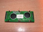
Sorry, Raits999, I was so focussed on deducing the pins that I missed out answering your main question; "how can I connect this to a PICAXE and if is possible". Well, I would certainly have a go! I would start with an PICAXE AXE132 driver board and pay very careful attention to the pinouts and the circuit diagram. The AXE132 module was designed originally for 2x16 LCD displays but now is used with modified software on 4x20 line OLED displays. It does not, however, cope with two controllers as the E1 and E2 pins on your device would indicate. But there are three spare outputs on the AXE132 module that can be addressed to bring them high or low. Therefore, I would have a play around with these, connecting to the E1 and E2 pins. Bring E1 high, send the data then bring E2 high and send the rest. I suspect that you have a 4 x 40 line display, each controller handling 80 characters.

You can download the datasheet on the AXE132 from PICAXE and that gives a useful little circuit diagram in the last few pages if you want to try and attach something like an 18M2 yourself. Download the code for the AXE134 and I think that this could probably be modified to drive the display that you have if you apply a little ingenuity.

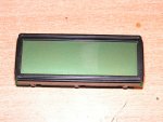
I am guessing that the display is, in fact, character-based. A graphic based LCD is less likely and is more involved in the software side.

So, how to start? Firstly, make sure that you can get the display up and running. Apply 5v to the Vcc/Vdd terminals and run a further connection through a 10K variable resistor to the Vee terminal. Try adjusting the VR and see if the display goes from transparent to black. If it does, then you are in business. Then it is a question of applying the AXE132 circuit diagram with the additional connections that I mentioned above. Patch the code and see what happens...

Also, before you do actually start, wait a day or two to see if anyone finds fault in what I have suggested or if anyone on this forum has any better ideas. Watch this space...and good luck! - I think that you are in with a chance.
 

raits999

Member
I have experimented this module on arduino and tried different pin configurations and (also the way you mentioned) run several glcd test programs but nothing not even changes in contrast as you can see normal character based lcd. Ultimately i'd like to run this module on picaxe but i'm afraid that it is to slow for directly driving glcd.
 

hippy

Ex-Staff (retired)
Of course, even if you can get the hardware interfaced, you then have to work out what the commands are to send to it. You might get lucky and find something similar and find they have the same command set but it will likely be much easier to get a GLCD that's completely documented working.
 
Top