Hi all,
This is for the same projects as a previous thread about PS/2 optical mouse. As before, I don't want to give away many details of the project because it might actually be valuable. I'd love to tell, you though, I'm quite pleased with an idea and we all know how that feels!
I've got a stepper motor I need to control, and it has to be that particular one because: 1) it's part of a gear train which has a very nice but unusual worm gear which I need; 2) it's nice and small. It's actually from a PSP disk laser drive unit.
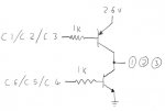
I don't know what the correct names to describe the stepper are, but I've figured out how it works. I've attached two images. The first is a schematic of the motor. It has 4 wires controlling it, call them "1,2,3,4". It has 6 coils, in 3 pairs. One end of each of these pairs are tied together on wire "1" (at the bottom of the image [1] ). The other end of each of the pairs is connected to one of the other wires "2,3,4". So it is possible to excite any coil pair by putting wire "1" high and one of "2,3,4" low (or visa versa).
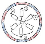
Around these coils is the moving part, which is a shell (cross section shown in schematic), which is magnetised with 5 poles. In the schematic, red = north, blue = south.
The second image shows the sequence to rotate one step. The red line represents the currently active magnetic attraction. I believe it sort of works like a variable reluctant motor - the rotation of the coils excited is the revers to the rotaion of the shell. But the shell IS magnetised. Sticking with the pin names 1,2,3,4, one step clockwise would look like this electrically:
Obviously, I'm trying to figure out how to interface with it.
Firstly, is there any way of working out what kind of current/voltage it's designed to take? The PSP it came from ran on a 3.6V Li-ion, but that's little to work with. The resistance of each coil pair is about 4 ohms. 3V seems to be the lower limit to actually make it move. That's (a rather large?) 750mA. The motor is only about 1cm diameter - the coils are small.
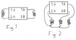
Secondly, are there any driver chips that exist for this type of motor? I've asked digikey and they've never heard of anything like it. I wondered about using a standard dual H-bridge. Normally, a dual H-bridge would have 4 outputs to control two coils, call them coil 1 and 2, so the four outputs would be 1A, 2A, 1B, 2B. Normally it would be connected as attachment 3 Fig.1. Could it instead be attached as in Fig.2? It would mean that 1A would need to be able to sink and source 1B and 2B, which it wouldn't normally be designed to do. Would this kind of use break it?
I also have some quad op amp lying around (AZ324, similar to LM324). Might that work? Just for simple high/lowing the required wires at the right time. Problems I see with that idea are that (again) it's not designed for that, and I would need to be able to have unused pins floating, which isn't possible with an op amp.
As always space is a premium so single (small) chip solutions would be best.
Thanks greatly in advance as always.
This is for the same projects as a previous thread about PS/2 optical mouse. As before, I don't want to give away many details of the project because it might actually be valuable. I'd love to tell, you though, I'm quite pleased with an idea and we all know how that feels!
I've got a stepper motor I need to control, and it has to be that particular one because: 1) it's part of a gear train which has a very nice but unusual worm gear which I need; 2) it's nice and small. It's actually from a PSP disk laser drive unit.
I don't know what the correct names to describe the stepper are, but I've figured out how it works. I've attached two images. The first is a schematic of the motor. It has 4 wires controlling it, call them "1,2,3,4". It has 6 coils, in 3 pairs. One end of each of these pairs are tied together on wire "1" (at the bottom of the image [1] ). The other end of each of the pairs is connected to one of the other wires "2,3,4". So it is possible to excite any coil pair by putting wire "1" high and one of "2,3,4" low (or visa versa).
Around these coils is the moving part, which is a shell (cross section shown in schematic), which is magnetised with 5 poles. In the schematic, red = north, blue = south.
The second image shows the sequence to rotate one step. The red line represents the currently active magnetic attraction. I believe it sort of works like a variable reluctant motor - the rotation of the coils excited is the revers to the rotaion of the shell. But the shell IS magnetised. Sticking with the pin names 1,2,3,4, one step clockwise would look like this electrically:
Code:
[U]1  2  3  4[/U]

1  -  0  -
1  0  -  -
0  -  -  1
0  -  1  -
0  1  -  -
1 - - 0Firstly, is there any way of working out what kind of current/voltage it's designed to take? The PSP it came from ran on a 3.6V Li-ion, but that's little to work with. The resistance of each coil pair is about 4 ohms. 3V seems to be the lower limit to actually make it move. That's (a rather large?) 750mA. The motor is only about 1cm diameter - the coils are small.
Secondly, are there any driver chips that exist for this type of motor? I've asked digikey and they've never heard of anything like it. I wondered about using a standard dual H-bridge. Normally, a dual H-bridge would have 4 outputs to control two coils, call them coil 1 and 2, so the four outputs would be 1A, 2A, 1B, 2B. Normally it would be connected as attachment 3 Fig.1. Could it instead be attached as in Fig.2? It would mean that 1A would need to be able to sink and source 1B and 2B, which it wouldn't normally be designed to do. Would this kind of use break it?
I also have some quad op amp lying around (AZ324, similar to LM324). Might that work? Just for simple high/lowing the required wires at the right time. Problems I see with that idea are that (again) it's not designed for that, and I would need to be able to have unused pins floating, which isn't possible with an op amp.
As always space is a premium so single (small) chip solutions would be best.
Thanks greatly in advance as always.
Attachments
-
 28.1 KB Views: 30
 -
 29.1 KB Views: 22
 ). All those transistors have a max collector current of over 800mA.