My schematic, couple questions.

Shafto

Senior Member
Searching around on google I found this on another forum in reply to someone's question about a filter for automotive transient suppression:

"My standard input & load-dump protection circuit is a series diode
followed with a series 47R 5W resistor. The clamp is a P 1.5KE-33
(or 30V, depending on the regulator) transzorb. That works for me
because most of my stuff runs on 100mA or less.

That's been working reliably for many years in both automotive and
industrial (24V) applications."


and


"I've done a number of designs for 28V military vehicles. The usual circuit is a high
side switch that turns off before the max. regulator input voltage is
exceeded. On the input side of this is an LC filter (primarily for EMC) and
the output side has a TVS to catch the fast transients. The circuit is
designed to handle 100V for 100ms and 250V for 1uS. It helps to have an
automotive regulator on the input to the equipment because it raises the
voltage at which you have to turn off the circuit and gives more flexibility
with the TVS voltage."


Some good solid information.. The top solution would work for only the picaxe I suppose... and I thought it unreasonable to have a choke that could handle the full power of the LEDs, but I just came across this 75amp coil that's well priced... it just says "100" for impedance, I assume that's uH? why does impedance use the omega symbol? isn't that for ohms? ..something else I don't quite get, when you see devices like this with their frequency.. what is what? frequency of what? of a reoccurring transient? or is it a speed thing again (how fast it comes on) like transistors where 300mhz = 3ns ? according to the graphs in the data sheet this thing looks like it holds good impedance right until 1000mhz or 0.1ns.. am I understanding this properly? is it like response time?

So following military design guy's plans would this coil make a good choice for an LC filter for the whole shebang? ..I dunno what cap to pair with that though.. the 022uF X2 I have? or something else would work better?... I found a better TVS than the one shown above:

http://production.littelfuse.com/data/en/Data_Sheets/5kp_revised.pdf

5000W bidirectional to catch all fast transients on the other side of the LC.. I can go with 24v, 26v or 33v.. maybe 26v? not a huge choice I guess.. I dont' really know where to begin with the high side switch though.. I could start looking around I suppose.

Plus a 30amp diode before the coil.. and the regs have their 6amp diodes still which will make them work less dropping voltage..

This with a 250V 0.1uF ceramic at the beginning of everything and hopefully I can be done with this! This (what sometimes feels like) filtering propaganda has been the biggest pain of the whole project!
 
Last edited:

Shafto

Senior Member
I see now I was confusing impedance with inductance.. I'll have to figure that out.. inductance causes impedance I guess.. like AC resistance? only 100ohm on the EMI might not be enough impedance to AC? how to I figure how much inductance causes a certain amount of impedance? what other variables are involved?

Something else I just realized is that this coil is a "common mode choke for emi" maybe that's not what I want? There is another category under "inductors, coils, chokes" just called 'fixed' where I find a 470nH 33.7amp coil.. Datasheet:
http://www.cooperbussmann.com/pdf/263f48f6-d8e1-4249-bee9-e64b52387e1f.pdf

maybe that isn't enough inductance? is this a better choice than the EMI filter? I really have no idea how to choose these parts yet.. what's the difference between the EMI choke and the other? tuned to certain frequency I suppose? looks like it covers a lot though..

Maybe like this?

12vRAW - 0.1uF 250V - 20AFUSE - 470nH+cap - TVS - Varistor - 30A Rectifier - 12vOUT - 1AFUSE - 1mH 1amp+cap - 4700uF 35v - 0.01uF - AUTO 5v reg - 0.01uF - Picaxe

I just don't know really how to pair the caps to the coils..

Am I bullet proof yet? for some reason I really feel like I need the beaniebots goahead here.. hah.
 
Last edited:

BeanieBots

Moderator
BeanieBots I think your're behind the 8-ball now ...lol :D
It would be nice to sink the "8" but it's not over yet!

@Shafto.
For me to give you the "goahead" would require me to see the final design including physical layout and dimensioned drawings of the looms.
Then I'd need to "do the sums". I don't mind spending a few minutes here most days giving empirical advice based on 40 years experience but to invest 3 days on a full detailed analysis is something I would charge my standard consultancy daily rate for.
It would be cheaper to fit a choke, cap, transorb, varistor & emi filter to each LED;)

I'll try to answer some of your questions.
470nH sounds a bit low but would be better than nothing.
I have several 100uH that are OK to 20A. They are 'disks' about 1" diameter and 1/2" long.

Balanced/emi/inductor.
Balanced & emi filter give you the grounding problem caused by your loads.
A 'simple' inductor is easier to understand and implement (properly) but even then you still need to get the grounding right.
They are 'different' rather than better or worse.
A balanced choke (the type used in an emi filter) is one with two windings. One for the line and the other for the load. It is wound such that the magnetic fields generated by the load current cancel each other out. That means that the load doesn't actually 'see' any inductance in series with line.
However, any current which only goes through one side, sees the full inductance. One of the key advantages is that the load current does not saturate the magnetic core which leaves more available for transient suppression. The disadvantage is that the load side 0v MUST NOT be connected to the line side 0v. Doing so would short out the 0v coil and worse than that, the shorted side would also (via magnetic coupling) short out the line coil rendering the filter useless.

Your coil marked "100" could mean anything!
"Typically" they are marked as uH.

Impedance of an inductor = 1/(2*PI*f*L) for a sinusoidal wave only.
The way an inductor reacts to a transient depends on the rise rate.
Rather than me try to explain it, here's a web based calculator which gives the equations:-
http://hyperphysics.phy-astr.gsu.edu/hbase/electric/indtra.html
Unfortunately, at very high dV/dt's you also need to factor the inductors capacitance between it's windings. That gets seriously messy in the sums and requires more information than that available in the average datasheet:eek:

Your final arrangement:-
Always put the fuse first.
Can't comment about the TVS. I don't know it.
100nF after the 1mH.
100nF decoupling on the PICAXE.

That should do the job short getting a scope on it with worst case signals applied to the front end.
Don't muck it all up with sloppy grounding:p
 

leftyretro

New Member
It would be nice to sink the "8" but it's not over yet!

@Shafto.
For me to give you the "goahead" would require me to see the final design including physical layout and dimensioned drawings of the looms.
Then I'd need to "do the sums". I don't mind spending a few minutes here most days giving empirical advice based on 40 years experience but to invest 3 days on a full detailed analysis is something I would charge my standard consultancy daily rate for.
It would be cheaper to fit a choke, cap, transorb, varistor & emi filter to each LED;)

I'll try to answer some of your questions.
470nH sounds a bit low but would be better than nothing.
I have several 100uH that are OK to 20A. They are 'disks' about 1" diameter and 1/2" long.

Balanced/emi/inductor.
Balanced & emi filter give you the grounding problem caused by your loads.
A 'simple' inductor is easier to understand and implement (properly) but even then you still need to get the grounding right.
They are 'different' rather than better or worse.
A balanced choke (the type used in an emi filter) is one with two windings. One for the line and the other for the load. It is wound such that the magnetic fields generated by the load current cancel each other out. That means that the load doesn't actually 'see' any inductance in series with line.
However, any current which only goes through one side, sees the full inductance. One of the key advantages is that the load current does not saturate the magnetic core which leaves more available for transient suppression. The disadvantage is that the load side 0v MUST NOT be connected to the line side 0v. Doing so would short out the 0v coil and worse than that, the shorted side would also (via magnetic coupling) short out the line coil rendering the filter useless.

Your coil marked "100" could mean anything!
"Typically" they are marked as uH.

Impedance of an inductor = 1/(2*PI*f*L) for a sinusoidal wave only.
The way an inductor reacts to a transient depends on the rise rate.
Rather than me try to explain it, here's a web based calculator which gives the equations:-
http://hyperphysics.phy-astr.gsu.edu/hbase/electric/indtra.html
Unfortunately, at very high dV/dt's you also need to factor the inductors capacitance between it's windings. That gets seriously messy in the sums and requires more information than that available in the average datasheet:eek:

Your final arrangement:-
Always put the fuse first.
Can't comment about the TVS. I don't know it.
100nF after the 1mH.
100nF decoupling on the PICAXE.

That should do the job short getting a scope on it with worst case signals applied to the front end.
Don't muck it all up with sloppy grounding:p
"Impedance of an inductor = 1/(2*PI*f*L) for a sinusoidal wave only."

Shouldn't that be Inductive Reactance = 2*PI*F*L (not the recipical)? Then impedance could be calculated by including any additional capacitance and resistance components?

Lefty


Lefty
 

BeanieBots

Moderator
Retrolefty.
You are absolutely correct. My foul up:eek:
Zc=1/(2*PI*f*C)
Zl=2*PI*f*L
(for sinusoids only)
Nice to see someone is sanity checking;)
 

Shafto

Senior Member
Thanks for more help..

I guess I'm trying to decide between the 2 coils.. the balanced choke would cause me to have to run my grounds from the LED arrays back to the board.. for the cost of the extra wire and terminals wouldn't really be worth it though? I think I'd be better off just to spend more on a fixed choke and keep the ground all the same.
here's the data for it.. I forgot to post it:
http://www.steward.com/web_info/CADPrints/Sales/CM5441Z101B-10-A-2.pdf

I really hate equations... I have no idea what half the symbols are, Zc? Zl?

In the link it wants series resistance? I don't have a series resistor.. There are all kinds of other load going on but how the hell do you choose 1 value for the whole circuit? and what about the time thing with the mhz? do I have that right? I see a "seconds" slot in the equation in the link.. but I don't quite know how to convert mhz to seconds.

So I've got 100ohm impedance @ 100mhz. I'm still lost on how to find out what kind of inductance this balanced choke has... but according to that link impedance is also a factor of how quickly the current tries to change.. so at 100mhz that's a really fast change I take it.. and 100ohm of impedance doesn't seem like a lot for that fast of a change... but I dunno.. I don't quite know how to get all the numbers out.

I could use a higher inductance fixed choke... a toroid I found, 20.5amp, 5uH.. I could use that instead of the 470nH.. there's nothing near 20amp in the 100uH range.. anything much higher than 5uH starts to become very cost prohibitive anyway...

So I shouldn't decouple the picaxe with 0.01uF? too bad.. I already have some.. but I can get some standard 50V 0.1uF ceramics for that..

And how to choose a capacitor to work with the inductor? a 0.1uF works well with the 1mH? would I then want less or more capacitance for the 5uH?

The max that will ever be drawn by the LEDs is 11620mA.. that would be with reverse lights on, brake lights on, and both signals lights on at the exact time all 8 channels on both sides are full... that won't happen.. RMS I'll probably never see more than 5-6amp.

Edit: I just remembered 1hz is like 1 second.. so 100mhz would be like 0.00000001 second? or 10ns?
 
Last edited:

BeanieBots

Moderator
Your gradually getting it:)
Forget the balanced choke if you don't want to run seperate grounds back to the board.
Zc = impedance due capacitance
Zl = impedance due to inductance
They are vectors, and the combined result involves root(-1).
If you don't like equations, then let's not go there.

For what it's worth (for the linked inductor). If Zl = 100R @ 100Mhz, then from Zl = 2*PI*f*L
L=100/(2*3.1416*100e6)=159nH @ 100Mhz (not very much).
But have a look at those graphs!
See how the inductance itself changes with frequency. Also note how much the CAPACITANCE of the inductor goes up with frequency.
You would need to put that data into a table and write a small program to calculate the actual response to a spike.

Go with the 5uH choke if that's the best you can get.
Keep to 100nF. You are after low ESR with the cap rather than aiming for a specific LC time-constant. The bigger the LC the better but transient response of the non-ideal component is more important in this application.

0.01uF decoupling is OK for the PICAXE but 100nF would be better.
I can't remember if you had a small electrolytic on the regulator output but if you have about 10uF then 0.01uF (10nF) will be fine. If not, either fit one (best) or increase the 10nF to 100nF and keep it close to the PICAXE.

You said "RMS I'll probably never see more than 5-6amp. "
Is that the average current drawn taking into account the PWM?
What would the current be if PWM stopped active high?
Will it take out the fuse? Can the rest of the circuit (including the LEDs) cope?
The "large" capacitor will 'see' a fair amount of ripple current due to the 11A PWM current. Make sure it has an adequate ripple current rating. If the rating is not specified, it won't be.
 

Shafto

Senior Member
I can understand equations once I can visualize what's going on.. not so much the other way around.. so examples and models really help me... I can see how the equation works now.. thanks.

For my application I see you say it's more important for low ESR to just use the 0.1uF caps with the inductors, but just for my own understanding.. what's the frequency thing all about? and the time constant? is that one and the same?

So for an example here... the ignition pulse transient in a car is only 3v, lasts 15uS, and is 3500hz continious.. so if you were making a filter specifically for that 3500hz you would want to make your LC filter resonate at a peak frequency of 3500hz to best deal with that?

..I realize that in making a 3500hz low pass filter you would most likely be covering a lot of other frequency range as well.. but for my design I don't need to be specific? that 0.1uF with both inductors cover a good range of frequency?

The 5v reg specified the use of a low ESR cap.. I used a 47uF tantalum.

About the current.. 5-6amp is a guess at the max it'll generally see... if PWM goes full high that's fine.. the LEDs are slightly derated their max current.. I only have PWM functions to exactly match brightness levels to stock... I'll break it down a little better..

168 red LEDs -series strings of 3 @ 70mA = 3920mA, marker lights will run around 8-20% DC, brakes probably around 80% DC

150 amber LEDs - series strings of 3 @ 70mA = 3500mA, 8 sequential channels flashing, 3500mA would be for less than 1 second.. and that's with hazard lights (rarely used) half that for 1 signal a side.. I dunno what average draw there is...

84 white LEDs - series strings of 2 @ 100mA = 4200mA, full power when on.. The most I can see myself drawing during average use would be parallel parking with a signal on, backing up, and braking...

Everything is well over rated.. and I've binned all the series groups of 3 LEDs so their added Vfs lead to a 64-67mA draw on each string.

Haven't received my white LEDs yet from Hong Kong, should be here this week... I ordered 30 a while ago and was very pleased.. so I got another 100 to do my reverse lights with...

The "large" cap is for the 5V reg though, which is only for the picaxe, the PWM current will be under 4000mA and will only be generated by the 9V regs.. does this still apply?


Here's some pics of the actual assemblies.. I have soldered before this.. but it was an occasional thing.. so please don't poke too much fun!

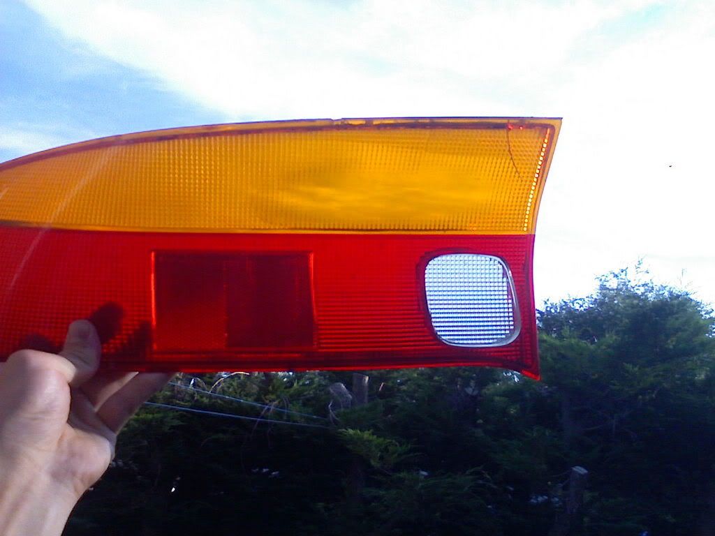
Stock lens before I painstakingly sanded it flat and buffed it out clear (well, a cracked practice piece):


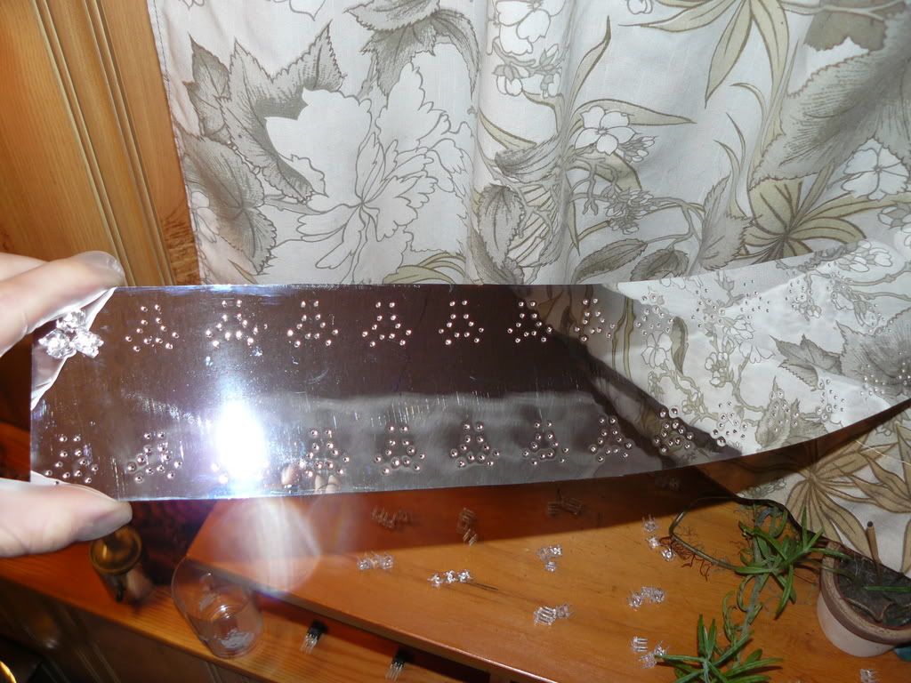
Reflective mylar laminated onto plexy for the boards:
(you can see on the shelf the LEDs I used, mirrored mylar is conductive so I had to cut out 1240 pieces of shrink tube for each lead of each LED to stick through the 1240 holes I drilled.. wheeew!


Back of boards:


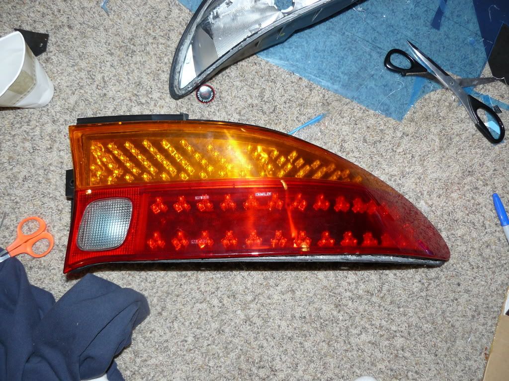
And the straight goods.. nothing is fastened yet.. but I had to put it all together to see how it looks! ..I'll be putting a strip of prismatic reflector between the 2 rows of red LEDs as well..

 
Last edited:

BeanieBots

Moderator
Umm.... No....
You are after flat DC. So, the time constant (Inductance * Capacitance) wants to be as large as possible.
With L's and C's you can only consider frequency in the basic equations when that frequency is a constant sinewave.
Transient suppression/filtering is WAY more complex.
Far too complex to go into with a text only forum. (requires special symbols just to write the formulae).
As a very crude example consider a square wave of 1 Hz.
Its frequency might be considered to be 1Hz but think about the rise time of the edge. That very fast rise in voltage is actually (at that instant) a very hgih frequency. In actual fact, a sqaure wave is made up from an infinite number of harmonics of the 1Hz with the highest being infinite frequency but at zero amplitude. If I had pen and paper I could draw it and expalin quite easily but too much efort for me to get out a package and sketch it up. Besides, I'd only be repeating what you could find a good book on the subject.

The absolute last thing you want in a power supply filter is any sort of resonance going on. That was one of my concerns a lot earlier on when I spoke about preventing "ringing". That is when the transient "kicks" the LC part of your filter and it "rings" like a bell hit by a hammer. If there is no damping (resistive part) then it may well ring.
By having a different value capacitor each side and a resistive clamp (the varistor) ringing is kept low because there are two frequencies which "feed" from each other's energy to keep going. The varistor (and DC resistance in the choke) dissipate energy each time the current passes from one capacitor to the other via the inductor. A bit like having two penudulums of different length hanging from a common (free to move) point with their weights dipped in a bucket of water. Even if you get one swinging, the other will absorb its energy and both will lose energy to the water in the bucket.
Hope that makes sense.

A quick Google found exactly the example I wanted.
http://www.allaboutcircuits.com/vol_2/chpt_7/2.html

I even found a simple text explanation of what goes on with the rapid rise of a transient and how you can break that down into "frequencies" so that you can do the sums on a basic calculator instead of having to write a custom program each time.
Thanks, at least I've managed to get something for myself out of all this.

http://www.dattalo.com/technical/theory/sqwave.html
 
Last edited:

Shafto

Senior Member
Umm.... No....
You are after flat DC. So, the time constant (Inductance * Capacitance) wants to be as large as possible.
With L's and C's you can only consider frequency in the basic equations when that frequency is a constant sinewave.
Transient suppression/filtering is WAY more complex.
Far too complex to go into with a text only forum. (requires special symbols just to write the formulae).
As a very crude example consider a square wave of 1 Hz.
Its frequency might be considered to be 1Hz but think about the rise time of the edge. That very fast rise in voltage is actually (at that instant) a very hgih frequency. In actual fact, a sqaure wave is made up from an infinite number of harmonics of the 1Hz with the highest being infinite frequency but at zero amplitude. If I had pen and paper I could draw it and expalin quite easily but too much efort for me to get out a package and sketch it up. Besides, I'd only be repeating what you could find a good book on the subject.

The absolute last thing you want in a power supply filter is any sort of resonance going on. That was one of my concerns a lot earlier on when I spoke about preventing "ringing". That is when the transient "kicks" the LC part of your filter and it "rings" like a bell hit by a hammer. If there is no damping (resistive part) then it may well ring.
By having a different value capacitor each side and a resistive clamp (the varistor) ringing is kept low because there are two frequencies which "feed" from each other's energy to keep going. The varistor (and DC resistance in the choke) dissipate energy each time the current passes from one capacitor to the other via the inductor. A bit like having two penudulums of different length hanging from a common (free to move) point with their weights dipped in a bucket of water. Even if you get one swinging, the other will absorb its energy and both will lose energy to the water in the bucket.
Hope that makes sense.
Those are some great explanations.. I read and understood before I saw your edit with the links.. "infinite frequency with zero amplitude" I can visualize that in graph mode in my noggin.. The information in the links would take me much longer to process.. I'll check them out in further detail later. Right now I'm gonna draw up my new filter design.. I should have 2 different value caps on either side of both inductors.. but values aren't that significant, correct?

0.1uF ceramic 250v - 5 uH - 0.22uF film X2

0.1uF ceramic 250v - 1mH - 0.001uF film X2

or should I use larger HV electrolytic caps on the ouput side? with a series resistor as well? what wattage should this resistor be rated for if this is the case?

I'll start drawing to make it easier to read.
 
Last edited:

BeanieBots

Moderator
Change the 0.001uF to 0.01uF.
Series resistor with first cap, maybe about 10R 0.5W should be OK.
I think Dippy had it up at 47R which IMHO is a bit high.
I'll wait for your diagram.
Goodnight (it's a "school" day!)
 

Shafto

Senior Member
The reason I put 0.001 is because I have one... if I have to buy something else.. should I just get another 0.22uF X2 for the output side of the 1mH coil? I'd like to make the best choice.

Edit: here's the latest for the filter...

 
Last edited:

Shafto

Senior Member
I'm rethinking that 30A diode.. I just realized that with a voltage drop of 1.2 or so.. @ 10A would create 12W of heat.. and so I'd need a heatsink I imagine...

I think I'll just stick to the 6 amp diodes I have before the regs.. with the 30amp there the voltage drops more than I like anyway.. I never actually added it up.. decimal numbers are deceivingly small.. that's how my digikey bills with a bunch of 1.xx, 2.xx, and 3.xx seem to somehow add up to so much when it doesn't seem like they should.. heh.

Maybe then just put a 3amp into the 5v reg instead of the 1amp? ..so it could handle any surging better without the 30 there.
 

BeanieBots

Moderator
D2 won't do a great deal for you anyway.
D3 is fine at 1A. Its main purpose is prevent C5 from being dumped during cranking or other brownouts.
Other than that, looking pretty damn good!
Would be nice to have a second opinion, I've not done any serious maths on it but "instinct & gut feel" says it should keep your PICAXE safe as long as you keep the grounding as actually shown.
 

Shafto

Senior Member
wohooo!

I guess I don't need the extra 1amp fuse for only the picaxe.. but it can't hurt..

As for the grounding.. I'm using a 2 sided board.. never designed a PCB before.. should I just make one whole side the ground plane? I don't really know..
 

BeanieBots

Moderator
You need to keep the 1A fuse unless your board's tracks/components can cope with 20A. It will also contribute a few ohms to your filtering.

My concern about grounding had more to do with where on the vehical you would be connecting the various 0v lines required by your entire circuit.
For example, the 0v at the battery terminal will be a very different 0v to that found at the chassis bonding terminal used by the existing tail-light assembly.
I don't know your car, nor do I want to get know it. I'm just pointing out where your remaining pitfalls are likely to be.
 

Shafto

Senior Member
I have grounding straps all over my car.. Everything under the bonnet is grounded by wire.. (I know how to speak in British about cars, I love Jeremy Clarkson, so glad his show is back now) The exhaust is also... then the exhaust is grounded again at the rear of the vehicle.. I figured that would be a nice good ground conductor.. you really can notice the operation smooth out when everything is grounded really well... so hopefully I"ll be ok on that front.. we'll see...

I was going to wait for a second opinion.. but I'm pretty anxious to hit the order button..
 
Last edited:

Mycroft2152

Senior Member
I think i was being a little too subtle...

Some people like to discuss the theory ad nauseum. others just built it.

We are having s snow storm, 8 to 14 in ches today! The first of the year.
 

BeanieBots

Moderator
Not yet, but it might be once the circuit is built and the "why do the lights come on every time I rev the engine?" questions start:eek:
 

Shafto

Senior Member
Haha.. please remember this is my first electronics project ever!

I know I should have started smaller.. and learned the basics.. and all that boring stuff.. just not the way I do things though.

I am inexperienced in electronics, but I am quite experienced at taking on ridiculous tasks that I had no prior knowledge of what-so-ever. That helps a bit..

I'm confident it will work in the car just like it does on the bench.. time will tell.

Either way I've got a new exciting hobby now.. I'm already envisioning all the other things in my life that could use a micro controller.. I think next I'll have to rig up some stepper motors on top of my shocks so I can adjust the damping while I'm inside the car.

..Since I've been building this I've seen at least 2 other threads where people were asking about putting a picaxe in a car.. well maybe this little filter, (or a variation without the 5uH LC and 12v out) should get posted up in finished project thread on it's own so someone can get a basic idea of what they need to do?

I'm very grateful for all the help I've had here.. I wouldn't be anywhere without this great forum.. I have not seen a donate button anywhere, but I'd like to. I did see something about donating for some kind of software development for picaxe but not the forum specifically, is there something?

..Anyway, I guess I'll make this second (hopefully last on this project) order from digikey.. then breadboard that bad boy out with the opto isolators and such.. and then get started on the PCB layout.

Thanks again!
 

Shafto

Senior Member
Alright.. I just finished breadboarding my circuit with the 40x1.. excluding the filter, as I can't fit those high power parts into the breadboard.. I'll just have to make the PCB before I test it in the car.

Everything worked first time I fired it up again.. I was happy about that... until an old haunting error occurred. When I turn the marker lights on, and then off, the LEDs somehow go full brightness... I tried tying down the PWM marker output with a 10k and then adding a "low portc 2" command.. but it doesn't help... after this occurs (LEDs at full brightness with no brake or marker input) sending the marking input high again will bring the LEDs back down to their proper level.. but the brakes become useless after this error, whether the markers are on or not the Brake PWM signal won't go to the LEDs when initiated.. they only go full bright.

But if I don't turn the markers on the brakes work fine, and if I turn them on, but not off.. everything will be ok.. it's only when the markers go off that I get this error.

It was happening with my 28X setup aswell but I thought I had cured it with the above mentioned.. I suppose it was just coincidence though.. as it's back now.. with the 28X I could stop it from happening by doing a new download of the code.. it would work for a couple times usually and then revert.. but before I rebuilt this 40x version it seemed to be working properly.. an intermittent problem.. the worst kind.

But it doesn't seem intermittent this time.. although it did work ok when I first fired it up.. the markers turned off fine instead of going full high.. but now it's back to this error state again and not even a new download does anything.. I can't figure this one out.. Any suggestions?

How can I make sure that when PWM marker goes off, the PWMout pin goes low and not high... I know it's that pin going high because if I disconnect it the LEDs aren't full bright.. they go back to normal.

It seems the pin used for PWM marker out sometimes turns off low, and sometimes turns off high.. I need to make sure it goes low.

..The only thing I can think of doing is telling the picaxe to reset itself when I turn the markers off... just run a wire from an output to the reset and just pulse it low when the markers go off? does that sound like an acceptable solution?

..Here's the code again:

Code:
init:

pwmout 1,255,0

main:
	
	readadc 0,b0		   'signal fade in time

	readadc 1,b1		   'signal fade out time

	readadc 2,b2		   'PWM duty cycle for marker lights
	  b3 = 4
	  w1 = b2 * b3

readadc 3,b6
b7 = 4
w3 = b6 * b7

pwmduty 1,w3

  	
	  If pin1 = b4 Then	   'No change in pin 1 (marker lights off)
  	  If b4 = 1 Then		   'Pin 1 is high      
  	    PwmDuty 2, w1		   'Update duty only   (adjust duty cycle if marker lights are on)
  	  End If
  
 	 Else				   'Pin 1 changed
    	b4 = b4 ^ 1                'Update b4 to reflect pin 1
   	 If b4 = 1 Then   	   'Pin 1 went high ...
   	   PwmOut 2, 255, w1  	   'Start PWM
   
 	 Else                 	   'Pin 1 went low ...
 	     PwmOut 1 off      	   'Turn off PWM

    
 	 End If
 	 End If


	if pin3 = 1 and pin2 = 1 then flashhazard

	if pin3 = 1 then flashleft

	if pin2 = 1 then flashright

	if pin3 = 0 and pin2 = 0 then main


goto main

flashleft:

	high portc 6		     'turn v.regs on for left side  

	high 0			     'first bank of LEDs high
	  pause b0			     'pause for fade in time
	high 1			
	  pause b0
	high 2
	  pause b0
	high 3
	  pause b0
	high 4
	  pause b0
	high 5
	  pause b0
	high 6
	  pause b0
	high 7
	  pause b1			     'keep last bank high for fade out time
	  pause b1
	
	low 7				     'last bank to turn on now goes off
	  pause b1			     'pause for fade out time
	low 6
	  pause b1
	low 5
	  pause b1
	low 4
	  pause b1
	low 3
	  pause b1
	low 2
	  pause b1
	low 1
	  pause b1
	low 0
	  pause b1

	low portc 6			     'turn left side regs off

	goto main

flashright:

	high portc 5		     'turn v.regs on for right side  

	high 0			     'first bank of LEDs high
	  pause b0			     'pause for fade in time
	high 1			
	  pause b0
	high 2
	  pause b0
	high 3
	  pause b0
	high 4
	  pause b0
	high 5
	  pause b0
	high 6
	  pause b0
	high 7
	  pause b1			     'keep last bank high for fade out time
	  pause b1
	
	low 7				     'last bank to turn on now goes off
	  pause b1			     'pause for fade out time
	low 6
	  pause b1
	low 5
	  pause b1
	low 4
	  pause b1
	low 3
	  pause b1
	low 2
	  pause b1
	low 1
	  pause b1
	low 0
	  pause b1

	low portc 5			     'turn right side regs off

	goto main

flashhazard:

	high portc 6		     'turn v.regs on for left side
	high portc 5		     'turn v.regs on for right side  

	high 0			     'first bank of LEDs high
	  pause b0			     'pause for fade in time
	high 1			
	  pause b0
	high 2
	  pause b0
	high 3
	  pause b0
	high 4
	  pause b0
	high 5
	  pause b0
	high 6
	  pause b0
	high 7
	  pause b1			     'keep last bank high for fade out time
	  pause b1
	
	low 7				     'last bank to turn on now goes off
	  pause b1			     'pause for fade out time
	low 6
	  pause b1
	low 5
	  pause b1
	low 4
	  pause b1
	low 3
	  pause b1
	low 2
	  pause b1
	low 1
	  pause b1
	low 0
	  pause b1

	low portc 6			     'turn left side regs off
	low portc 5			     'tuen right side regs off

	goto main
 
Last edited:

Shafto

Senior Member
ok, fixed now with this code.. I was still using leftover code from before the PWMduty command.. I realized I could just use pwmduty 2,0 and that keeps the pin from stopping PWM all together and then just sitting there high making my lights as bright as can be...

Code:
init:

pwmout 1,255,0                   'turn on PWM signal for brakes
pwmout 2,255,0                   'tuen on PWM signal for markers

main:
	
	readadc 0,b0		   'signal fade in time

	readadc 1,b1		   'signal fade out time

	readadc 2,b2		   'PWM duty cycle for marker lights
	  b3 = 4
	  w1 = b2 * b3

      readadc 3,b6               'PWM duty cycle for brake lights
      b7 = 4
      w3 = b6 * b7


	pwmduty 1,w3                    'update PWMduty for brakes


	if pin1 = 1 then pwmduty 2,w1   'if pin1 goes high turn on marker lights
	end if

	if pin1 = 0 then pwmduty 2,0    'if pin1 goes low turn off marker lights
	end if


	if pin3 = 1 and pin2 = 1 then flashhazard

	if pin3 = 1 then flashleft

	if pin2 = 1 then flashright

	if pin3 = 0 and pin2 = 0 then main


goto main

flashleft:

	high portc 6		     'turn v.regs on for left side  

	high 0			     'first bank of LEDs high
	  pause b0			     'pause for fade in time
	high 1			
	  pause b0
	high 2
	  pause b0
	high 3
	  pause b0
	high 4
	  pause b0
	high 5
	  pause b0
	high 6
	  pause b0
	high 7
	  pause b1			     'keep last bank high for fade out time
	  pause b1
	
	low 7				     'last bank to turn on now goes off
	  pause b1			     'pause for fade out time
	low 6
	  pause b1
	low 5
	  pause b1
	low 4
	  pause b1
	low 3
	  pause b1
	low 2
	  pause b1
	low 1
	  pause b1
	low 0
	  pause b1

	low portc 6			     'turn left side regs off

	goto main

flashright:

	high portc 5		     'turn v.regs on for right side  

	high 0			     'first bank of LEDs high
	  pause b0			     'pause for fade in time
	high 1			
	  pause b0
	high 2
	  pause b0
	high 3
	  pause b0
	high 4
	  pause b0
	high 5
	  pause b0
	high 6
	  pause b0
	high 7
	  pause b1			     'keep last bank high for fade out time
	  pause b1
	
	low 7				     'last bank to turn on now goes off
	  pause b1			     'pause for fade out time
	low 6
	  pause b1
	low 5
	  pause b1
	low 4
	  pause b1
	low 3
	  pause b1
	low 2
	  pause b1
	low 1
	  pause b1
	low 0
	  pause b1

	low portc 5			     'turn right side regs off

	goto main

flashhazard:

	high portc 6		     'turn v.regs on for left side
	high portc 5		     'turn v.regs on for right side  

	high 0			     'first bank of LEDs high
	  pause b0			     'pause for fade in time
	high 1			
	  pause b0
	high 2
	  pause b0
	high 3
	  pause b0
	high 4
	  pause b0
	high 5
	  pause b0
	high 6
	  pause b0
	high 7
	  pause b1			     'keep last bank high for fade out time
	  pause b1
	
	low 7				     'last bank to turn on now goes off
	  pause b1			     'pause for fade out time
	low 6
	  pause b1
	low 5
	  pause b1
	low 4
	  pause b1
	low 3
	  pause b1
	low 2
	  pause b1
	low 1
	  pause b1
	low 0
	  pause b1

	low portc 6			     'turn left side regs off
	low portc 5			     'tuen right side regs off

	goto main
But I'm still having some flicking problems.. it's not as bad as it used to be.. but I can't get rid of it.. even with the duty command... but if I plug in the value I get from doing a debug instead of using a variable there is no flickering at all...

This PWM business sure is finicky on this picaxe.. I've tried using all the different little tidbits of code people have suggested and nothing completely gets rid of the flicker... someone must have encountered this in a previous project?

This is getting pretty frustrating, I'm convinced there has to be some way to store the value I get from the ADC like a constant.. that will only change when I change the input POT.. I just want it to look like it does when I use a constant value for the PWM duty... only with the ADC input.. surely that must be possible.
 
Last edited:

moxhamj

New Member
Which pin is flickering, and which line of code works with a debug but not without a debug? We need to narrow down the problem. It still is a bit vague whether it is an input error or an output error. It could well be noise getting into an ADC input but there are about another 10 other possibilities as well. Read values from ADCs will be constant if the pot is near the picaxe, the impedence is 10k or so and there are no noisy signals nearby and the power supply is stable. But put the circuit near an ignition coil and it will behave completely differently.
 

Shafto

Senior Member
it's not near anything right now.. it's just on the bench...

Both of the PWMout pins cause flicker in the array.. but only when using a variable.

if I use this:

"pwmduty 2,w1"

I get flicker.. if I debug b1 and get 5, then multiply by 4 to get 20 (the value w1 reads) and plug that in like this:

"pwmduty 2,20" I get the exact same brightness level.. but absolutely no flicker


the 10k pot for the divider is right beside the ADC input, the wire going to the input is less than 2cm away.


...I just want to to behave like it does when I use a constant value.
 
Last edited:

eclectic

Moderator
bytes and words ?

Shafto.
I'm still half asleep here, so I'm not sure, but;

readadc 2,b2 'PWM duty cycle for marker lights
b3 = 4
w1 = b2 * b3

readadc 3,b6 'PWM duty cycle for brake lights
b7 = 4
w3 = b6 * b7

Is there a conflict between the byte and word variables?
(See Manual 2 pages 9 & 10)

What would happen if you used say w4 and w5 instead?

e
 
Last edited:

moxhamj

New Member
I agree with eclectic - pick w4 and w5 that are not used in any way anywhere else in the code. You could also see if
w4=20
pwmout w4...

causes the same error.
 
Last edited:

Shafto

Senior Member
Thanks.. I had thought that the word value was supposed to either be a product or sum of it's byte values.. not that the byte values that made the word had to be seperate.. and the word takes up 2 more byte values.. little misunderstanding there... but the funny thing is it doesn't seem to matter!

..Unfortunately there's no difference.. still getting flicker.. here's my code now:

Code:
init:

pwmout 1,255,0                   'turn on PWM signal for brakes
pwmout 2,255,0                   'tuen on PWM signal for markers

main:
	
	readadc 0,b0		   'signal fade in time

	readadc 1,b1		   'signal fade out time

	readadc 2,b2		   'PWM duty cycle for marker lights
	  b4 = 4
	  w3 = b4 * b2

      readadc 3,b3               'PWM duty cycle for brake lights
      b5 = 4
      w4 = b5 * b3


	pwmduty 1,w4                    'update PWMduty for brakes


	if pin1 = 1 then pwmduty 2,w3   'if pin1 goes high turn on marker lights
	end if

	if pin1 = 0 then pwmduty 2,0    'if pin1 goes low turn off marker lights
	end if


	if pin3 = 1 and pin2 = 1 then flashhazard

	if pin3 = 1 then flashleft

	if pin2 = 1 then flashright

	if pin3 = 0 and pin2 = 0 then main


goto main

flashleft:

	high portc 6		     'turn v.regs on for left side  

	high 0			     'first bank of LEDs high
	  pause b0			     'pause for fade in time
	high 1			
	  pause b0
	high 2
	  pause b0
	high 3
	  pause b0
	high 4
	  pause b0
	high 5
	  pause b0
	high 6
	  pause b0
	high 7
	  pause b1			     'keep last bank high for fade out time
	  pause b1
	
	low 7				     'last bank to turn on now goes off
	  pause b1			     'pause for fade out time
	low 6
	  pause b1
	low 5
	  pause b1
	low 4
	  pause b1
	low 3
	  pause b1
	low 2
	  pause b1
	low 1
	  pause b1
	low 0
	  pause b1

	low portc 6			     'turn left side regs off

	goto main

flashright:

	high portc 5		     'turn v.regs on for right side  

	high 0			     'first bank of LEDs high
	  pause b0			     'pause for fade in time
	high 1			
	  pause b0
	high 2
	  pause b0
	high 3
	  pause b0
	high 4
	  pause b0
	high 5
	  pause b0
	high 6
	  pause b0
	high 7
	  pause b1			     'keep last bank high for fade out time
	  pause b1
	
	low 7				     'last bank to turn on now goes off
	  pause b1			     'pause for fade out time
	low 6
	  pause b1
	low 5
	  pause b1
	low 4
	  pause b1
	low 3
	  pause b1
	low 2
	  pause b1
	low 1
	  pause b1
	low 0
	  pause b1

	low portc 5			     'turn right side regs off

	goto main

flashhazard:

	high portc 6		     'turn v.regs on for left side
	high portc 5		     'turn v.regs on for right side  

	high 0			     'first bank of LEDs high
	  pause b0			     'pause for fade in time
	high 1			
	  pause b0
	high 2
	  pause b0
	high 3
	  pause b0
	high 4
	  pause b0
	high 5
	  pause b0
	high 6
	  pause b0
	high 7
	  pause b1			     'keep last bank high for fade out time
	  pause b1
	
	low 7				     'last bank to turn on now goes off
	  pause b1			     'pause for fade out time
	low 6
	  pause b1
	low 5
	  pause b1
	low 4
	  pause b1
	low 3
	  pause b1
	low 2
	  pause b1
	low 1
	  pause b1
	low 0
	  pause b1

	low portc 6			     'turn left side regs off
	low portc 5			     'tuen right side regs off

	goto main
 

Shafto

Senior Member
hmm... I'm starting to develop a theory here...

I'm using 18turn precision potentiometers.. I can see each one of the 256 steps as the array dims... it seems if I really try and dial in a setting I can get rid of the flicker.. or pretty close.. sometimes there's still a little blip every 10 seconds or so...

I'm thinking maybe these potentiometers are too precise? it's too easy for them to be at a position in the middle of 2 ADC values?

If I turn the pot knob very very slowly I can see the LEDs step up to the next brightness level, flicker like crazy.. and then the flickering slowly goes away as I keep turning (talking about maybe 3-4 degrees of turning in total here) and then just before I see the next step of brightness I get a lot of flicker again.. and the whole cycle repeats for each of the 256 levels of brightness I can see.

What do you guys think? sound plausible?

..and if so.. what to do so solve the problem? can I code in some kind of hysteresis?

Or something I've seen before but have never used.. 10k digital pots.. 256step.. maybe that would be a good idea?
 

moxhamj

New Member
Sounds like a feedback loop somewhere - eg read a value, change something and the changing upsets the next value. I'm suspecting the power supply rails that supply the pots. What would happen if you read the value once per second, then go into a loop that outputs that value continuously for at least a second. Then read the values back using debug - it will then be slow enough to see if the values are changing and over what range.

You could also try 0.1uF caps between each of the ADC inputs and ground - this will smooth the adc inputs.

And going back to the original schematic, there is one 0.01 between 5V and ground. As a general rule, use 0.1uF and maybe even look at 0.1uF across the power pins of every chip. And also a 22uF somewhere across the 5V supply as well.
 
Last edited:

evanh

Senior Member
You've got analogue!? I'd missed that. You plan on keeping them in the final circuit?

Analogue needs careful construction to keep noise at a minimum:
- Ensure that digital ground and supply are run separately where possible. Paying particular attention to separating high current paths.
- For set levels, eg: pots, use a small capacitor to ground at the chip input.
- For dynamic signals it's wise to add shielding.

Software wise, adding hysteresis and/or filtering to the sampling code helps a lot. Lowpass filtering is good for accuracy but is not so good at removing jitter. I'd just add hysteresis for the moment:
Code:
markers_readSP:
    readadc 2,newsample
    if mSP_falling then markers_dimming
    if newsample > mSP then markers_done
    if mSP - newsample <= 1 then return   ; Hysteresis (1 keeps it tight)
    mSP_falling = TRUE
    mSP = newsample
    return

markers_dimming:
    if newsample < mSP then markers_done
    if newsample - mSP <= 1 then return   ; Hysteresis
    mSP_falling = FALSE

markers_done:
    mSP = newsample
    return
PS, I'm a little rusty on the picaxe so that prolly won't tokenise without some syntax fixups.
 

evanh

Senior Member
- Ensure that digital ground and supply are run separately where possible. Paying particular attention to separating high current paths.
That could have been worded a bit better. What I meant is to keep the analogue ground and supply rails mechanically separated from all the other rails.


Evan
 

hippy

Ex-Staff (retired)
If I turn the pot knob very very slowly I can see the LEDs step up to the next brightness level, flicker like crazy.. and then the flickering slowly goes away as I keep turning (talking about maybe 3-4 degrees of turning in total here) and then just before I see the next step of brightness I get a lot of flicker again.. and the whole cycle repeats for each of the 256 levels of brightness I can see.

What do you guys think? sound plausible?

..and if so.. what to do so solve the problem? can I code in some kind of hysteresis?
No matter how well designed, an ADC input can be sitting right on the edge of being one reading or another, the smallest amount of noise can flip it between the two. Even with smoothing capacitors on the input and power rails it can flip, although likely less frequently.

If you can keep the voltage in the middle, between the bottom and top flipping points, you will be fine ( and capacitors will help there, keeping ripple from going too high or low ), but any variable input such as with a pot will at some point be on a flipping point. That's what you're seeing as you adjust the pot; if you jumped the pot to the middle of the next voltage point you wouldn't see any flicker unless the input were excessively noisy.

Hysteresis is the solution, that can be simple or complex. The simplest solution is to not respond to any input change unless it's significant ...

- ReadAdc pin, this
- If this > current+1 Or this < current-1 Then
--- current = this
- End If

That's quite brutal and limits the resolution ( number of steps ). A better way is to always allow the level to increase or decrease but not to change direction unless it's a significant change ...

- ReadAdc pin, this
- If direction = GOING_UP Then
--- If this >= current Then
----- current = this
--- Else
----- If this < current-1 Then
------- current = this
------- direction = GOING_DOWN
----- End If
--- End If
- Else
--- If this <= current Then
----- current = this
--- Else
----- If this > current+1 Then
------- current = this
------- direction = GOING_UP
----- End If
--- End If
- End If

That works much better but it doesn't allow single bit changes in the opposite direction to the way the level was going. To handle that you need to add some sort of timer which can keep track of whether it's changing rapidly or holding its value ...

- ReadAdc pin, this
- If direction = GOING_UP Then
--- If this >= current Then
----- current = this
----- counter = 0
--- Else
----- If this < current-1 Or counter <= -COUNT_NEEDED Then
------- current = this
------- direction = GOING_DOWN
------- counter = 0
----- Else
------- counter = counter - 1
----- End If
--- End If
- Else
--- If this <= current Then
----- current = this
----- counter = 0
--- Else
----- If this > current+1 Or Or counter >= COUNT_NEEDED Then
------- current = this
------- direction = GOING_UP
------- counter = 0
----- Else
------- counter = counter + 1
----- End If
--- End If
- End If

If the unwanted variations of input are greater than one bit it can get even more complex and you're into averaging and even slowly ramping the current level towards that average to minimise changes and flickering. Smoothing capacitors on the input and power rails and good electrical design will help keep the bit change to within one bit.
 

Shafto

Senior Member
Thanks guys.. I'll try implementing this code shortly.. and a 0.1uF on the input to the pots..

I imagine the coding gets easier with time? that must be way it's called a 'language' ..when I first look at all that stuff my head spins.. takes me a few mins to really dig through it and understand what's going on.. but if I can barely reverse engineer it I dunno how the hell I'd come up with something like that on my own... hah.. wouldn't happen.. Maybe in time.

I'll try implementing the code shortly with a 0.1uF on the input to the pots.


..Is it customary to use digital pots for ADC inputs? ..would that just solve the issue without bulking up the code? ..apparently it just has 256steps that click all the way through.
 
Last edited:

BCJKiwi

Senior Member
This is the code I currently use to produce an output change when ADC has changed enough to warrant resetting pwmout.

Don't know if this achieves the same thing that Hippy is suggesting or what you need.

The 'resolution' of the changes can be adjusted by changing the '15' in the line;
If b0>15 then pwmduty 2,w1
to what ever you want.

I only use the Word value for the pwmout as I wanted to use the lowest frequency (switching a MOSFET) and therefore needed a value > 255 in the variable. Otherwise you could just use a byte value throughout.

Code:
#picaxe 28x1
SetFreq m8

 
Init:
'LED Power Rail
pwmout 2,249,512                             ' establish pwm pin, Period(frequency), Duty & in midrange.
'
'
Main: 
LEDPower:                                       ' Vary LED Intensity depending on ambient brightness
 
ReadADC 0,b0                                  ' read ambient light intensity
let w1=b0*4                                    ' *4 to suit pwm Duty of 249
ptr=0                                             ' set scratchpad pointer to 0
 
If b0=>@ptr then let b0=b0-@ptr        ' test to see if READADC value INcreased.
elseif @ptr=>b0 then let b0=@ptr-b0   ' test to see if READADC value DEcreased.
EndIf
 
If b0>15 then pwmduty 2,w1              ' If READADC changed enough - change output Duty.
@ptr=w1/4                                      ' store LDR value of last PWMOUT change to scratchpad 0
EndIf
 
Last edited:
Top