This is a modified copy of my posting regarding the slow-speed PWM:
The routine below calls an interrupt at regular time intervals. The period can be modified by changing the EVENTS_PER_SEC constant.
Overall, no need to use an external chip (555 or the like), this solution has the Picaxe do everything. At the same time it is applicable to any case where you want to execute a piece of code in the background at regular intervals - as close to multitasking as the Picaxe can get. Just replace the toggle command with anything you like. If you make it a selection based on a counter (you can even use timer modulo some the number of tasks) you can implement (non-preemptive) multitasking in a round-robbin manner, i.e. first interrupt calls subroutine 0, second calls subroutine 1, and so on, then start again with subroutine 0. The only requirement is that each subroutine MUST be well-behaved, i.e. finish and return before the next interrupt comes in.
Wolfgang
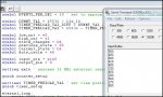
Code:
' uses internal timer to do slow-speed PWM on pin 0 (needs 28X1)

symbol EVENTS_PER_SEC = 240 ' set to twice the required PWM frequency (actually, slightly higher because of interrupt overhead)

symbol DUMMY_VAL = 65536 - t1s_16
symbol TIMER_PRELOAD_VAL_DIFF = DUMMY_VAL / EVENTS_PER_SEC
symbol TIMER_PRELOAD_VAL = 65536 - TIMER_PRELOAD_VAL_DIFF


setfreq em16

settimer TIMER_PRELOAD_VAL ' set time preload value
gosub timer_setup

eternal_loop:
    pause 4000 ' sleep for 1 sec, or do something else
goto eternal_loop

interrupt:
    toggle 0 ' do whatever is needed, in this case toggle pin to produce square wave output
    gosub timer_setup
return

timer_setup:
    timer = 0xffff ' generate interrupt at next overflow
    toflag = 0 ' clear timer overflow flag
    setintflags %10000000,%10000000 ' interrupt on timer overflow
return