Multiple Battery Cell Balancer

Solar Mike

New Member
I need a cell balancer for a three separate 48 volt banks of 8 series 6v lead carbon batteries; these are 300 AH sealed gel batteries and are proving difficult to get 100% balanced; once in a balanced condition, they will probably remain in that state and require little intervention.
Another requirement is to measure each individual cells voltage and raise some sort of alarm if any drop or go above set limits.

A simple balancing solution would have a voltage reference and voltage comparator attached to each cell, turning on a resistive load of several amps via a mosfet switch whenever the cells voltage went above a set point (7v in this case). Once the battery bank is near fully charged to 56 volts the charge current is only 1-2 amps, so it doesn't take much of a load on any runner cells to prevent them over charging.
Perhaps a 08M2 would do the job here, measure the cell voltage, turn on a mosfet, communicate with a Master Manager via opto-couplers, means using lots of cpu's but they are not that expensive compared to the $700 cost of each 6v battery.

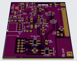
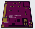
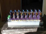
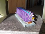
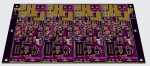
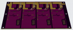
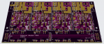
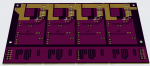
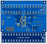
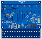
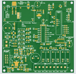
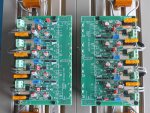
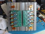
Here is my initial schematic, uses all smd devices to keep the pcb size down, each one fits onto a 50x62mm pcb designed to fit vertically across the resistor bank mounted on a heatsink. They are linked together via 10 pin ribbon IDC back to the master (yet to be designed), however each can be setup to run stand alone initially.
Schematic_BalModule.PNG


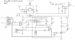
Note each cpu board sits at various battery cell potentials, so have to be initially programmed in a test jig prior, I imagine once a Master is connected it could alter voltage set points from a central point.

Will post the pcb soon...

Cheers
Mike
 
Last edited:

papaof2

Senior Member
Looks like a good start.

Would the master be polling the PICAXEs or would each PICAXE set a pin high/low to indicate it has new data? Or would the PICAXE run data collection in a loop and only notify the master if the most recent voltage reading is out of limits? How would the master notify a PICAXE that the voltage limits it's looking at need to be adjusted?

Polling ensures that the master knows all the PICAXEs are alive. Lots of things can affect PICAXE serial data in and out so you may want one of the serial interfacing gurus to give a blessing on your plans for that - there is a 2-wire power + serial data network which includes addressing other PICAXEs as well as sending and receiving data among them ;-)

I suspect the knowledgeable folks here might want a day or two to do the wiring and component value verifications and start the "Would it be better if..." discussions - and they'll certainly want to see the code.
 

Solar Mike

New Member
Each battery cell module communicates via opto coupled common Input and an outputs all in two parallel streams; makes sense for a master to poll each one as required to get any data; so each has to have a unique cell address to prevent multiples attempting communications at the same time.

The protocol as yet undecided would have a number of master commands, ie broadcast to all units a min-max voltage, a single address to get data from an individual cell monitor.

The communications may not be serial, as it is hard wired, could go with a simple pulse width scheme where the width of a pulse determines a slave address, width of 2nd pulse determines function required and a reply is a pulse width that is say a voltage reading in ADC units like 10us per unit. The system doesn't have to be fast, just reliable.
 

Solar Mike

New Member
Here is the cell module pcb, 50 x 62mm, the boards will mount edge on vertically direct to the pcb hosting the 50w aluminum shell resistors bolted to a heatsink, the ribbon cable runs across their tops. I am using 2 ohm load resistors - 3.5A for the 6v battery cells balancing at 7v.

This scheme has a central balance point, rather than having individual balance boards wired at each battery. Having long 2.5mm^2 balance wires running to each battery cell means voltage drops should an adjacent module be balancing at the time of a voltage measurement; part of the coms protocol could be a broadcast command, turn off any balance loads for 100mSec to allow an accurate measurement.... perhaps.

Top:
26040

Bottom:

26041
 

Solar Mike

New Member
Here is the load module pcb for eight cells, its quite large, 240x76mm; sits above the 50W load resistors bolted to a thick alloy plate acting as a heat sink and will form one side of a box possibly. Automotive 10 amp fuse holders for standard fuses solder direct to the board, a disconnect plug\socket goes to the battery.
I may place an intermediate pcb between this board and the actual battery cell leads, it will have heavier plug\sockets for the wires; as I'm also experimenting with an 8 cell inductive balancer that I designed a while ago as it requires bigger cables to keep the lead resistance down, see link here for more details Inductive Balancer.

26042

Master controller is next, will wait a while on that, too many other projects require finishing first.
 

Solar Mike

New Member
Decided to make a pcb for initial connection of the battery balance wires, fuse in series with each wire, will make it easier and safer during experimentation with various balancer designs. The 9.5mm screw pcb sockets can take up to 4mm wire - required for the inductive balancer.

81x87mm pcb fits inside a 115x90 plastic box with a clear lid (AliExpress), I can bolt this at the end of each battery bank of 8 cells.

26043

Once I have a working tested system, will post the gerber files here.

Cheers
Mike
 

Solar Mike

New Member
Testing this project now, have assembled 8 cpu boards and writing some initial software to see how effective it is when connected to 8 series 200AH Lifepo4 cells. First smd 08M2 cpu I tried didn't work, could not connect to it, tried other boards and they worked fine. Replaced the cpu with another and it works ok too.

Just purchased these from the PicAxe store, seems perhaps the faulty cpu may have had no basic boot loader in it, hard to tell, had to chop its leads off to get it cleanly off the board, hope the remaining ones are ok.

Cheers Mike
 

Solar Mike

New Member
Here are a couple of photo's showing how the unit is assembled.
26107


26108


I have set it up for Lifepo4 cells, stand-alone, no master controller, so the voltage regulator, opto couplers etc are not required.
Have used 1 ohm power resistors (3.5A balance current) bolted to the heatsink, the module carrier pcb is supported by the resistor connection wires,
Each cell module sits vertically held up by its 3 connections to the carrier pcb.
Setup is very easy, connect a 3.5v (balance Voltage) psu between each cell input in turn, and adjust the set pot until the balancing led turns on, then connect via the 9pin input connector to the cells using 1.5mm^2 cables.

I tested it on a group of very old extremely unbalanced 40AH cells, works a treat, only issue is it takes up a lot of space due to the heatsink and modular assembly format, obviously an active balancer would be more efficient. The sample code fits on the 08M2LE lower memory version currently on sale.

Edit: those power resistors are not flat, you have to sand down the bottom by rubbing on a piece of emery paper on something flat like a sheet of glass, use WD40 or similar as lubricant, once flat they will transfer their heat much better to the heatsink.

Cheers
Mike
 

Attachments

Last edited:

Solar Mike

New Member
Have started to build a battery box to house 16 Lifepo4 cells and the above balancer layout is rather bulky as two are required, was planning to place the balancer at the end of the case, its messy to have cooling fins protruding out of the case; so a after a re-think, have whipped up a new pcb layout that doesn't use a carrier board, but has four cell modules on a single pcb with small cables going to each power resistor; circuit remains the same.

The new layout means groups of 4 pcb's can be placed atop one another or flat next to each other with the load resistors separate; the end of my case will be a sheet of 3mm aluminum approx 300 x 300mm, I can bolt the resistors to that, allowing any heat escape the box.

Have a few 12v batteries to make up also, having a single pcb with 4 cell modules seems easier.

New boards are 137 x 86mm:
26110

26111


Edit: Why build one when on AliExpress there are hundreds of various inexpensive balancers for sale; with large 100-400AH cells unless they are well matched, a high current balancer is required, a lot of the stuff out there is cheap junk, I wouldn't trust a lot of it with expensive batteries, also none of them work with 6v lead carbon batteries. I prefer DIY, then I know how it will perform, and I can repair it.

Cheers
Mike
 
Last edited:

Solar Mike

New Member
Have made a change to the design of this board, seems pointless to have an IDC plug\socket on every cpu slave board, have placed a 10pin IDC on the input and output only, the output one can be left off and jumper wires used to join up multiple boards as required. PCB size remains the same. Input IDC ribbon goes to the master controller.
26115
26116

Working on a controller board now. Will try to keep it as simple as possible, sorry about the smd components for anyone whom wants to make one, I have ditched all through hole resistors caps etc, many IC's are now not available in through hole format anymore.

Cheers
Mike
 

Solar Mike

New Member
Yet to finally decide how I want to show to the user, status of the cell balancing operation, in many instances these batteries are in some paddock somewhere powering some pump or other; there is no one to see any display. Simplest method perhaps is some sort of serial output from the main master controller, to that effect have gone to a 32 led string driven via serial input constant current drivers, two 16 output chips used here. For 48v only 16 leds need populating etc.

I have used an 14M2 cpu to manage the leds, pulse them off\on etc, low level serial battery state data is aggregated by the master and sent to this display board. At some later date I could replace the leds with say a 4 line lcd or a more graphical display, without having to re-engineer the master board, if that makes any sense.

The display board 100x92mm has a bit on the bottom that can be cut off with tin snips and used as a front panel overlay. Most of the components are mounted under the pcb, so the top mounted 3mm leds can shine through holes in the case\box top. The actual pcb will be in black, blue here to easily see tracks.

Top:
26117

Bottom:
26118

Currently there is no schematic for any of this project, gone straight to pcb, if it works ok, I will draw one up, for simple pcbs like this I generally don't bother with schematics, until everything is working and finalized.

Cheers
Mike
 
Last edited:

Solar Mike

New Member
Completed the controller, 100x100 pcb; using a Picaxe20M2 to run everything.
As up to 32 opto-coupled slave boards can be used for a 96v Lifepo4 battery bank, have used a power mosfet driven by a Fan3111 driver for the TX serial output and a dual logic schmitt trigger for the RX input. The optional 32 led display board above has been altered slightly to also employ an opto coupler for its RX input, the controller also has an LCD serial output if the display module is not used.
A number of multi-turn trim pots are used for setting the Pack Max\Min voltages and individual cell Max\Min values, 3 relays are used to turn off battery loads or Input PV, these switch high power vacuum relays powering the main inverter and input to PV controllers.
26119

Have sent the gerbers off to get made, will be an interesting project to get up and running. Files attached if anyone wants to have a play, sorry no schematic yet.

Cheers
Mike
 

Attachments

Solar Mike

New Member
Boards have come back from JLCPBC, they look good; will test them out in the next 2-3 weeks, very busy on another project, adding a bank of LifePo4 cells (24v 200AH) in parallel with an existing 24v 300AH bank of lead carbon batteries in a small off grid system. The sealed LC batteries have a low bulk charge voltage of 27.8v which maps quite well to the Lifepo4 (8 series cells); theory being the LFP bank will take most of the load initially before the LC bank starts to flatten. The 8 cell balancer will be fitted to the LFP bank and the 4 cell version to the LC bank.

Cheers
Mike
 

fernando_g

Senior Member
Very nice project! It seems that you have the system complete now, and my comments will be late, but I will still provide my two yen :

Don’t use a potentiometer to adjust the voltage divider, rather use a pair of 1% resistors. With the top one being 30k and the bottom 10k, you’ll have exactly 2.0 volts with an 8.0 volt input.

The LDL1117 regulator has a +/-5% tolerance if I recall correctly. You may accept that error, or want to include a software calibration correction.

Lastly, have you checked the power Mosfet’s data sheet to ensure that the channel is fully enhanced with only a 3.3 volt drive? A google search doesn’t show valid data sheets for the part number in the schematic.
 

Solar Mike

New Member
Power mosfet Data sheet 100N02, spec for low as 2.5v drive.
I normally use fixed resistors, when I have an on board accurate voltage reference, in this case there isn't one, so have opted for an 20T pot, have found these are ok provided they are not continually played with, which makes their wiper contact unreliable.

Haven't built this yet, still working on other projects.

Cheers
Mike
 

Solar Mike

New Member
Here are a couple of photos for an 8-cell version of the balancer, using 3.5 amp balancing resistors, no communications and no master, working in stand-alone mode. Heatsink is a scrap piece of alloy wall siding material. The 200AH Lifepo4 battery cells are not that well matched, thus the high balance current requirement.

Using the 08M2LE smd version cpu currently.

Edit: Note the bottom of those 25 watt resistors are not flat and have to be filed flat using some 200 grit sand paper on a sheet of glass with a little kerosene as lubricant, only then do they make good contact with the heatsink.

26178

26179
 
Last edited:

papaof2

Senior Member
Good solution for getting the best heatsink contact.

My LiFePO4 projects are not YET that big - the 4 cell 10AH battery which replaced the AGM battery in the equipment shed lighting system is the biggest so far and that BMS is very small because the lighting load is just over 1 amp. The in-progress project is an 8 cell battery pack for an 810 watt pure sine wave UPS (replacing the two original 12 volt AGM batteries which lasted 6+ years). The BMS is rated for 20 amps to match the label on the Litto-Kala 6.5AH cells used for the battery pack - although I have seen the same Litto-Kala cells advertised at 30 amps and higher. The typical load on the UPS will be under 200 watts so if the inverter in the UPS is 80% efficient the battery current at that load would be around 9.1 amps. I tend to build conservatively as my UPS units with LiFePO4 batteries are intended to have "lifetime" batteries. At my age, that might not need to be much more than 10 years...

I track your progress because I have plans for a solar system with a battery bank near 1000AH and that system might need something larger and smarter ;-)
 

papaof2

Senior Member
I've been dealing with chronic back pain for several years and have exhausted the pain relief levels of a "patch" 7 day system (Butrans) and I've now been moved to an inside the cheek (buccal) "12 hour" system (the "patient information" documents for that Rx read "This could kill you if").

My backup plans using solar have been put on hold because I can no longer manage 50+ lb panels so I'm looking more at generator- or line-charged backup. It's pointless to run a generator 24 hours a day for home power when that gen could charge a battery bank in a few hours and then you could have 24 hours of silent power - less wear on the gen so more years of use, less fuel used, less noise that might attract unwanted attention.

Having a fine-grained record of the power used by the hour is a place I could use the PICAXE logger to monitor certain things for a day or more to get that detailed record of power usage - usage by the quarter hour or perhaps finer is much better than the "YY kWh over XX hours" data a KillAWatt or similar can provide. That would also provide useful bits such as WHICH hours the fridge or the freezer or the <your choice here> was on and whether using digital timers to shift the hours of operation of certain appliances to provide a smaller maximum load and a more even load on that battery backup system and limit or reduce the heating of the inverter or other parts of the system. Being able to reduce the peak load should also increase the run time of the battery bank by some (possibly small) amount.

There are lots of places our little electronic slaves (PICAXE and others) can be very helpful ;-)
 

Solar Mike

New Member
I am a bit wary of pre-packaged server rack batteries, certainly the less expensive ones out there can have very dodgy componentry.
In the past month or so I have pulled apart 4 of these 100AH 48v batteries due to internal faults, blowups and am very dismayed at the crappy level of construction. Cells are generally taped together in groups of 4, busbars are not flexible, so this allows for stress on the terminals and resulting failures.

Because everything is out of site of the user, shortcuts can and are taken, even the cells themselves don't meet advertised spec. Of the 4 packs dismantled, I have managed to reassemble some of the good cells to make new battery packs, thus the requirement for a higher current balancer due to mismatched cells.

If you go and talk to an installation company whom uses these pre-packaged batteries in various off grid setups, they are bound to have a few dead ones lying around; the effort to dismantle and repair is not worth it, so they sit there unused waiting to be re-cycled, if that's even possible; here in NZ there seems to be no recycling options for them, other than disposal at the tip.

With the stand-alone balancer, after dong some testing, with 3.5 amp balance loads, the cables need to be larger, currently using 1.5mm^2 and there is interaction between adjacent balancers inputs due to cable voltage drops, this can be fixed by using less current or thicker wires or altering the pcb slightly so each cell has its own pair of balance wires; have changed the pcb and sent gerbers off today.

The master\slave setup will not suffer from this, as each slave will be sent a synchronizing pulse to tell them to turn off any loads and measure the cell voltages now unloaded.

Cheers
Mike
 

lbenson

Senior Member
Mike--your efforts are very impressive. Daunting, though, for less talented and less adventursome folks.

I've seen youtube teardowns of the Vatrer server rack battery, and the vlogger was impressed with both cell quality and build quality. YMMV.

"Having a fine-grained record of the power used by the hour is a place I could use the PICAXE logger to monitor certain things"

I'm fortunate that my power company provides usage charting for billing period by day, and for each day by hour. They will even provide a guesstimate of appliance usage--water heating, washer/dryer, etc., and a big category of "other". This has given me a really good idea of what usage is and how it is timed.

I've also added Sonoff wifi switches to certain loads--boiler, freezer, water pump (the fridge outlet is difficult to access). Here's a chart which shows when they run.

26181

The top 7 lines show inside and outside temperatures, and the temperature of the zone pipes on my 3-zone boiler. The 3 sets of colors below the 0C mark show when my freezer (red), well pump (blue) and boiler (purple) ran. These time-on / time-off readings come from the Sonoff switches which have been flashed with the Tasmota firmware. (I'd like to get rid of the freezer--I'm not sure it has been openned in the past 3 months.)

Apologies, Mike, for going OT.
 

Solar Mike

New Member
Yes our power Co has online total consumption readings over every 1/2 hour interval, for more granular data I used one of those wall plugin power meters on individual equipment like fridge freezer etc. We have 2 fridges and a freezer which occasionally can all start simultaneously, potentially their motors drawing quite large spike currents, as these run off a small inverter (12v Lithium Battery), the inverter has to handle this without shutting down.
 

lbenson

Senior Member
occasionally can all start simultaneously
Yes, that's a big issue. If I get as far as powering essential appliances from a battery in a grid-down situation, I'm considering using sonoff switches to assure that when the sump pump is on, the well pump cannot start up. It may be that a bigger battery will make for a less complex setup.
 
Top