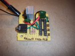
I don't have this project board so I am only looking at the way it appears in the datasheet. If you have a multimeter you should be able to compare the diagram in the datasheet and your board to get a better understanding of what goes where. When you talk about the 0v holes I think you are misunderstanding them. On the diagram it appears that the outside rows of holes are positives but the inside rows are the inputs to the picaxe and the outputs from the darlington.
EDIT but zooming in on the photo, the outputs might be the other way round. Manual3 page 7
http://www.picaxe.com/docs/picaxe_manual3.pdf explains how to use the darlington chip. Maybe it would be a good idea to experiment with the board first with some LEDs and resistors or perhaps a small motor, to get a better understanding before you build it into your main project.
Looking at the datasheet page 2
http://www.picaxe.com /docs/axe117.pdf and your youtube drawing it appears that your 11 wires to the breadboard are all connected together (all battery + from the picaxe board).
The darlington chip supplies the negative to an device that already has a positive. Normally with this board you would connect these 6 devices between the two holes next to each row of the darlington. If you make the input high, the output goes low, but not the other way round. If you make the input low the output is high impedance (a bit like not connected).
Outputs
To move this over to your breadboard you would take the 6 wires from the column under the 0v to the breadboard. These would connect to the 6 devices on your breadboard that already have a positive from the supply on your breadboard. You will also need to connect the 0v line of the picaxe board to the 0v of the breadboard supply. This way these devices will get the voltage that is on your breadboard but will be controlled by the picaxe. Also the darlington positive should be connected to the breadboard supply instead of the picaxe supply. This may involve bending that pin up before you fit the 2003 in the socket and then soldering a wire to it. This board doesn't appear to be ideally suited to controlling items at a different voltage to the picaxe.
Inputs
Similarly you would need to take the 5 input lines from the 0v column to your breadboard. You may also need to take one positive wire to your breadboard. KEEP THIS SEPARATE. It does not connect to your positive on the breadboard, otherwise your breadboard would be trying to charge your batteries. Any switches on your breadboard would need to connect between this wire and one of the 5 other input wires. Any picaxe input that needs to connect to the output of any other device on your breadboard would need to be discussed individually to make sure it is at the correct voltage.
If your breadboard is already running between 3 and 5 volts you would not need the batteries on the picaxe, you could join the 2 supplies together instead. Don't do both.
If you don't want to use the darlington chip you would take your outputs from the row of holes down the middle of the board. These would be used for low current outputs between these holes and 0V.
Don't be in a rush to do anything, give others a chance to review my thoughts as it's late at night and I don't even have this board to test.