most accurate pwm frequency
- Thread starter aduy
- Start date
Andrew Cowan
Senior Member
Can you elaborate on your question?
Using the PWMout command, all frequencies are equally accurate (or inaccurate) as a percentage - it depends on the clock speed of the PICAXE's core.
PICAXE's using an external resonator will be more accurate than ones using the internal one.
Why are you asking - what's the application?
A
Using the PWMout command, all frequencies are equally accurate (or inaccurate) as a percentage - it depends on the clock speed of the PICAXE's core.
PICAXE's using an external resonator will be more accurate than ones using the internal one.
Why are you asking - what's the application?
A
Andrew Cowan
Senior Member
Do you mean the most steps between fully on (100%) and fully off (0%)?
I've found using PWM on a white led quite easy to implement, the dimming of it happens rather smoothly which is probably what you want to do with RGB led, you just need to use three outputs with PWM, I'd be testing it in a breadboard or something, the PWM command is very easy to use and I'd reckon you would knock it over in a few hours of playing, have fun... *thinks* I must try that myself....
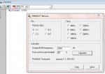
Get yourself a copy of PICMulticalc.
It will give you the information on resolution etc. for different clock speeds and your favourite frequencies.
But, as Andrew says, ultimately the absolute accuracy is down to the accuracy/stability of your clock. The resolution is down to your settings choice.
It will give you the information on resolution etc. for different clock speeds and your favourite frequencies.
But, as Andrew says, ultimately the absolute accuracy is down to the accuracy/stability of your clock. The resolution is down to your settings choice.
Most resolution?well what i mean which frequency would give me the most resolution. im going to be using the pwm to control some rgb leds
At 4MHz, ~3920kHz
See Man.2, p.165,
and the Wizard Pwm.
Mind you, whether you'll see
all the steps is another matter.
")
e
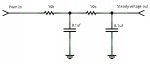
yes that is what I mean. I need to filter the pwm, because the rgb leds are going to be spinning on my bike spokes, although i could do some cool strobe things and make it so the wheels look like their not spinning. I have 6 "104"(0.1uf) ceramic capacitors so if i do a two pass filter I think i can use 10k resistors.Do you mean the most steps between fully on (100%) and fully off (0%)?
so does that mean for 8mhz its 7840 and so on for other core frequenciesMost resolution?
At 4MHz, ~3920kHz
Attachments
-
 26.8 KB Views: 16
Last edited:
1. Why do you need to filter?yes that is what I mean. I need to filter the pwm, because the rgb leds are going to be spinning on my bike spokes, although i could do some cool strobe things and make it so the wheels look like their not spinning. I have 6 "104"(0.1uf) ceramic capacitors so if i do a two pass filter I think i can use 10k resistors.
so does that mean for 8mhz its 7840 and so on for other core frequencies
2. Yes, 3920 @4MHz or 7840 @ 8MHz will allow over 1000 brightness "levels".
e
Attachments
-
 42.8 KB Views: 12
I'm confused - but as we know, that ain't difficult.
Are we doing 2 topics in one here?
1. How to smooth the power to reduce/prevent strobe effect.
2. Choosing a PWM frequency to get the most duty steps/resolution.
I realise they can be related; after all (going to extremes) a 10MHz PWM would probably mean no perceivable strobe on your bike wheels so smoothing not required.
If you want to go the smoothing route then your design will depend on the LED power required.
I would be tempted to have a bench-test before going OTT with PWM resolution. When I was playing with a design I had 100 steps for each RGB channel and that was well OTT as duties of 50,50,49 and 50,50,48 (R,G,B) were no different to my eyes.And that was BEFORE I went to the pub!
BTW; PICMultiCalc: Although it's aimed at PIC programmers it does give good information wrt accuracy and duty steps for a given clock and chosen PWM. PIC derives it's values using a sequence of dividers so (generally) as you get to the higher end of the frequencies the accuracy and resolution decrease. You may select 50 or 51% but there is no difference.
So, whilst it's not aimed specifically at PICAXE programming it does provide a useful reference as to the 'goings on' in PIC.
- but as we know, that ain't difficult.Are we doing 2 topics in one here?
1. How to smooth the power to reduce/prevent strobe effect.
2. Choosing a PWM frequency to get the most duty steps/resolution.
I realise they can be related; after all (going to extremes) a 10MHz PWM would probably mean no perceivable strobe on your bike wheels so smoothing not required.
If you want to go the smoothing route then your design will depend on the LED power required.
I would be tempted to have a bench-test before going OTT with PWM resolution. When I was playing with a design I had 100 steps for each RGB channel and that was well OTT as duties of 50,50,49 and 50,50,48 (R,G,B) were no different to my eyes.And that was BEFORE I went to the pub!
BTW; PICMultiCalc: Although it's aimed at PIC programmers it does give good information wrt accuracy and duty steps for a given clock and chosen PWM. PIC derives it's values using a sequence of dividers so (generally) as you get to the higher end of the frequencies the accuracy and resolution decrease. You may select 50 or 51% but there is no difference.
So, whilst it's not aimed specifically at PICAXE programming it does provide a useful reference as to the 'goings on' in PIC.
hippy
Ex-Staff (retired)
I think you are confusing two things here; PWM used via an RC circuit to set a voltage / brightness level and additionally turning PWM on and off to strobe the LED's.yes that is what I mean. I need to filter the pwm, because the rgb leds are going to be spinning on my bike spokes, although i could do some cool strobe things and make it so the wheels look like their not spinning.
Though the LED on and off signal looks somewhat like a PWM pulse train it's usually not described in those terms as it needs to be synchronised to wheel rotation. To do that there will usually be a magnet at a fixed point on the wheel and a sensor on the wheel fork. When the sensor triggers there will be a delay, then the LED ( or PWM ) is turned on for a short time then off again. This would more correctly be called "phase control" or similar.
geezer88
Senior Member
Veering a little further off course, please not that your eyes respond to brightness in a logarithmic manner. For example, a doubling of light value is just barely perceptible. So, the challenge will be to get the widest dynamic range of values, not the greatest resolution. Others advised to do some bench testing, and I heartily agree.
tom
tom
Well if you know the RPM , the PWM frequency and duty you could actually dig out your calculator and work some figures. i.e. what fraction of the rotation would be on or off.
And also it depends how you generate your PWM.
Some people do R then G then B very rapidly.(.e.g my Chinese made garden light which has now died).
When I was doing some code-generated RGB I had all 3 channels started together.
You could get some nice effects.
And also it depends how you generate your PWM.
Some people do R then G then B very rapidly.(.e.g my Chinese made garden light which has now died).
When I was doing some code-generated RGB I had all 3 channels started together.
You could get some nice effects.
A Picaxe 28X2 (latest version)well i was going to use 3 08ms to control each led individually, but how is it that you can control all three leds with just one pwm output? do you use transistors, or relays or something like that?
has four Pwmout outputs,
and a much greater processing power.
But first, to avoid confusion,
what exactly
are the effects that you hope to achieve?
Flashing / fading / RGB / "Knight Rider" .......?
e
OK, dead easy.just to change colors not anything too fancy, like go all the way through the spectrum and then back
How many LED's?
How will they be arranged / spaced?
e
What sort of RGB LED's?4 rgb leds, spaced every 90degrees on a 26 inch diameter wheel, 11 inches from the center.
Common Anode or Common Cathode?
And preferably, can you post a datasheet reference.
e
here its these from sparkfun, except i bought them from somewhere else for cheaper, but still the same leds. theres a link to the data sheet
http://www.sparkfun.com/products/105
http://www.sparkfun.com/products/105
OK, getting there.
Common Cathode 20mA
http://www.sparkfun.com/datasheets/Components/YSL-R596CR3G4B5C-C10.pdf
I assume that each colour is wired in parallel, as in
all Red on together / all Green on together
or something different?
And, the big question:
the physical wiring?
How do you plan to connect the LED's/ Picaxe/Power
to the spokes?
e
the picaxe is going to be soldered onto a prototyping board, with a socket and then all the red leds are going to be together, and the same for the blue and green. its all going to be powered by 2 AAs and its all attached to the wheel, with the leds taped or possibly glued to the spokes.