mrburnette
Senior Member
See it: http://www.youtube.com/watch?v=9kZOqdeUl2w&feature=youtube_gdata
Aug Aug 9, 2011 - Moved from Main Forum
26, 2011 - Synced 20X2 and 08M2 code base: http://www.picaxeforum.co.uk/showthread.php?19123-Morse-Code-Decoding-8WPM-with-a-PICAXE-08M2&p=178278#post178278
Notes:
I undertook this project as a challenge from a buddy. Special thanks to Peter Anderson and Ron Hackett for their support to the PICAXE community and for all of the material that they post - it is great scaffolding!
The code that I am posting is preliminary, but working. You will spend about $8 U.S. for all parts, less if you already have some components in your junk box. This is not a fancy circuit; the challenge was for a bare-minimum decoder, so almost everything I could do, I did in software which means that the audio input to the PIC is also minimal... very minimal and essentially does only one thing: It clips the audio signal due to saturation of the NPN transistor. Because we are talking saturation, a minimum of approximately 0.75V must be available from your PC or shortwave radio when listening to the Morse signal. My Dell does this easily on the Wikipedia test signals: http://en.wikipedia.org/wiki/Morse_code but I have downloaded some MP3 files which do not have the amplitude to clip the transistor, so additional work will be required to enhance the front-end. There are plenty of examples of amplifiers on the web, so I will NOT present anything here... do a bit of research or design and post for the community. An OpAmp will likely be the answer with some RC filtering. An excellent article on this is available: http://www.electronics-project-design.com/HamRadioCircuit.html Here is the SPICE for the 1 transistor signal clipper:
$ 1 5.0E-6 119.19350207351468 77 5.0 50
v 144 368 144 96 0 0 40.0 5.0 0.0 0.0 0.5
w 144 96 256 96 0
t 256 272 368 272 0 1 -4.99999999889 1.0999999999041585E-10 100.0
w 256 96 368 96 0
r 368 96 368 256 0 10000.0
w 368 288 368 368 0
w 368 368 144 368 0
w 368 256 448 256 0
g 368 368 368 400 0
R 480 80 576 80 0 5 100.0 0.7000000000000001 0.0 0.0 0.5
r 192 160 192 272 0 2200.0
w 192 272 256 272 0
x 73 240 101 246 0 24 5V
x 465 265 585 271 0 24 5V inverted
x 450 62 544 68 0 24 1V pulse
g 576 96 576 112 0
w 192 80 192 160 0
w 192 80 480 80 0
o 7 64 0 34 7.654505172902097 9.765625000000001E-205 0 -1
o 10 64 0 35 0.5846006549323611 1.8268770466636287E-4 0 -1
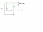
Copy the SPICE code into the clipboard, go to http://www.falstad.com/circuit/ with a JAVA enabled browser and select File Import to get the circuit diagram. The signal I labeled "5V Inverted" is tied to the 20X2 pin 11 (B.7). Your PC/Shortwave headphone out MUST generate 0.7V or more to saturate the gate and square-up the signal.
Before the Basic Code, I want to explain how the algorithm that I designed for the decoding works... I'm sure there are a zillion algorithms, but this one was devised to be fast and simple and easily fit into the EEPROM space of the 20X2. A timing loop monitors transitions on pin B.7 and counts within each cycle of the clipped-square wave on B.7. When a SPACE is detected, the logic sets another counter (Flag) and then goes about making the decision on DIT or DAH based upon the frequency count (not in Hz, but a relative count) that was obtained from the tight timing loop which monitors B.7.
For every DAH identified in the stream, a binary weight is applied based upon the position of the DAH... that is, first, second, third, fourth, or fifth element. DITs are not weighted but are counted with DAHs to achieve a total element count of DITs + DAHs in the character. The DAH-weights are bits 3-7 in a calculated index and the elements number make up bits 0-2.
Examples:
E = "DIT" Therefore, there are no DAHs and only one element. The pointer is %00000001 Index = 1
F = "DIT DIT DAH DIT" and the DAH is in the third position (bit 5 set) Pointer = %00100100 Index = 36
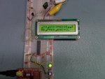
Note that I am NOT decoding any 6-bit Morse, therefore only the alphabet A-Z and numbers 0-9 are decoded in this preliminary code sample. I have tested this at 9600 BAUD on an old Scott Edwards serial LCD 16 Chars X 2 Lines but as coded below, it is intended to be used with your PC HyperTerminal at 19.2KB
Basic code attached.
- Ray
Aug Aug 9, 2011 - Moved from Main Forum
26, 2011 - Synced 20X2 and 08M2 code base: http://www.picaxeforum.co.uk/showthread.php?19123-Morse-Code-Decoding-8WPM-with-a-PICAXE-08M2&p=178278#post178278
Notes:
1. The 08M2 and the 20X2 code are identical except that the 20X2 is running at 64MHz and therefore can decode up to 15+ WPM while the 08M2 maxes out around 10WPM (I have seen the 20X2 decode 29WPM/17Farnsworth with ARRL training files.) However, since this is primarily an experiment with algorithms and not chips, I have elected to just post the full 08M2 code rather than 2 code sets.
2. For added fun, build a Morse code oscillator that runs between 700Hz and 800Hz and feed the clipper circuit with the output. This will give you immediate feedback in your key timing for learning or bushing up on your code.I undertook this project as a challenge from a buddy. Special thanks to Peter Anderson and Ron Hackett for their support to the PICAXE community and for all of the material that they post - it is great scaffolding!
The code that I am posting is preliminary, but working. You will spend about $8 U.S. for all parts, less if you already have some components in your junk box. This is not a fancy circuit; the challenge was for a bare-minimum decoder, so almost everything I could do, I did in software which means that the audio input to the PIC is also minimal... very minimal and essentially does only one thing: It clips the audio signal due to saturation of the NPN transistor. Because we are talking saturation, a minimum of approximately 0.75V must be available from your PC or shortwave radio when listening to the Morse signal. My Dell does this easily on the Wikipedia test signals: http://en.wikipedia.org/wiki/Morse_code but I have downloaded some MP3 files which do not have the amplitude to clip the transistor, so additional work will be required to enhance the front-end. There are plenty of examples of amplifiers on the web, so I will NOT present anything here... do a bit of research or design and post for the community. An OpAmp will likely be the answer with some RC filtering. An excellent article on this is available: http://www.electronics-project-design.com/HamRadioCircuit.html Here is the SPICE for the 1 transistor signal clipper:
$ 1 5.0E-6 119.19350207351468 77 5.0 50
v 144 368 144 96 0 0 40.0 5.0 0.0 0.0 0.5
w 144 96 256 96 0
t 256 272 368 272 0 1 -4.99999999889 1.0999999999041585E-10 100.0
w 256 96 368 96 0
r 368 96 368 256 0 10000.0
w 368 288 368 368 0
w 368 368 144 368 0
w 368 256 448 256 0
g 368 368 368 400 0
R 480 80 576 80 0 5 100.0 0.7000000000000001 0.0 0.0 0.5
r 192 160 192 272 0 2200.0
w 192 272 256 272 0
x 73 240 101 246 0 24 5V
x 465 265 585 271 0 24 5V inverted
x 450 62 544 68 0 24 1V pulse
g 576 96 576 112 0
w 192 80 192 160 0
w 192 80 480 80 0
o 7 64 0 34 7.654505172902097 9.765625000000001E-205 0 -1
o 10 64 0 35 0.5846006549323611 1.8268770466636287E-4 0 -1
Copy the SPICE code into the clipboard, go to http://www.falstad.com/circuit/ with a JAVA enabled browser and select File Import to get the circuit diagram. The signal I labeled "5V Inverted" is tied to the 20X2 pin 11 (B.7). Your PC/Shortwave headphone out MUST generate 0.7V or more to saturate the gate and square-up the signal.
Before the Basic Code, I want to explain how the algorithm that I designed for the decoding works... I'm sure there are a zillion algorithms, but this one was devised to be fast and simple and easily fit into the EEPROM space of the 20X2. A timing loop monitors transitions on pin B.7 and counts within each cycle of the clipped-square wave on B.7. When a SPACE is detected, the logic sets another counter (Flag) and then goes about making the decision on DIT or DAH based upon the frequency count (not in Hz, but a relative count) that was obtained from the tight timing loop which monitors B.7.
For every DAH identified in the stream, a binary weight is applied based upon the position of the DAH... that is, first, second, third, fourth, or fifth element. DITs are not weighted but are counted with DAHs to achieve a total element count of DITs + DAHs in the character. The DAH-weights are bits 3-7 in a calculated index and the elements number make up bits 0-2.
Examples:
E = "DIT" Therefore, there are no DAHs and only one element. The pointer is %00000001 Index = 1
F = "DIT DIT DAH DIT" and the DAH is in the third position (bit 5 set) Pointer = %00100100 Index = 36
Note that I am NOT decoding any 6-bit Morse, therefore only the alphabet A-Z and numbers 0-9 are decoded in this preliminary code sample. I have tested this at 9600 BAUD on an old Scott Edwards serial LCD 16 Chars X 2 Lines but as coded below, it is intended to be used with your PC HyperTerminal at 19.2KB
Basic code attached.
- Ray
Attachments
-
9.9 KB Views: 281
-
 22.3 KB Views: 155
Last edited: