This posting describes a Picaxe 20X2 controlled model tram so why is it in the communications section?
Because it is one of four functionally similar units that share a garden track network having two intelligent turnouts (points) and four buffer stops. The trams run unattended and have to pass each other to run from end to end. All six units also share a 2.4GHz radio network.
The logic problem to be solved was to begin with two, three or four operational trams set in any order next to one another on a particular straight section. The trams would then converse by radio and organize themselves to each reach a buffer stop. The furthest tram would then work its way to the nearest stop, passing the others by using the points. The process would repeat endlessly with the ‘furthest’ becoming the new ‘nearest’.
Democracy turned out not to be the best way to run a railway. It was easier to give the management task to one of the intelligent points and create a ‘radio central’. The next posting will be for this master turnout which sends instructions to the remote turnout and to the trams.
A separate posting will cover a self contained ‘radio sniffer’ that listens in to all the conversations and interprets them using a semi-graphic display.
The Track
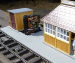
Peco G-45 track uses nickel silver rails 45mm apart on flexible plastic sleepers. The rails do not rust but do tarnish so electrical conduction can be a problem; however everything here is battery operated. The track is set 60cm off the ground to avoid the usual garden debris and make the models easier to appreciate. The longest section is 8m and 1/4 of the way along there is a turnout to a 4m section set at right angles. About 1m from the end of this, the master turnout gives access to a 3m siding.
The turnout controllers use a 9g servo to throw the points. All the trams so far constructed carry a tiny NdFeB magnet and the controllers detect the direction of passage of a tram using two reed switches. A two-second delay and the points switch over so even in ‘simple’ mode a single tram uses the whole track end to end.
The Trams
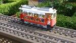
Scaled 1:24 these four short wheelbase trams are modelled in Sketchup from museum archives and online holiday snaps and videos. Construction is model grade plywood, lime, beech and ramin. The motor units use PCB material drilled to accept G-45 wheelsets and held in place with wooden sections. A Hostaform gear is drilled out to push fit onto one axle and is driven by a worm using a common B size motor. Scale speed is around 9 mph.
This particular tram runs in the Tibidabo pleasure park outside Barcelona. A fleet of tramvia blau run all weather but the red open sided ‘La Jardinera’ runs in the summer. The challenge this model posed was where to hide all the electronics but still have access.
Underneath and behind the false axle boxes and springs are two twin AA battery boxes, two HC-SR04 ultrasound modules, a double pole power switch, and the motor unit. In the false ceiling above and behind the striped awnings is the main circuit board, NRF24L01 radio module and a 9g servo. To rotate the trolley pole a full 180 degrees it is mounted on a 10 tooth pinion with a 40 tooth gear linked by brass rod to the servo horn. The servo is accessed by removing the resistive speed control elements on the roof. So much easier with electronic speed control these days.
Connections between the two compartments use rainbow coloured ribbon cables that blend into the decor. Above the heads of the passengers a LED20 IR detector pokes through the ceiling. The use of the IR remote input allows the mode of operation to be set to simple or radio.
Ultrasound Detection
A critical component for this project is the ability to detect, not just end of track, but any other obstruction on the way. The HC-SR04 modules worked beautifully on the bench giving distance feedback up to 5 feet away. This information can be used with the PWM speed control to slow proportionally before coming to a halt. Testing on the track, however, the tram would not move at all. The ultrasound was bouncing back off every sleeper! Originally the tram chassis hid the modules well away from view, now they are right at the edge and angled up to avoid the sleepers. Of course the detection range is diminished such that there is a danger of the tram idling onto the obstruction. Rather than just turning off the motor power it is now necessary to apply a short reverse pulse to effect positive braking.
The trigger pulse to the HC-SR04 is easy but the echo will have started before a pulsin command will be effective. Only part of the return pulse is of use here so just accumulating the state of the pin is enough to compute the value.
Radio Module
NRF24L01 2.4GHz modules have been covered elsewhere but here they are an important part of this project. Maximum voltage is low so the four AA rechargeable cells are split giving two supplies. The pinning of the modules is two rows of four set 0.1 inches apart. An 8-pin DIL socket is cut in two, reversed and soldered onto the main board. If there are height restrictions the pins of the module may be cut a bit shorter.
Picaxe 20X2 has easy to use SPI instructions. The NRF24L01 has a lot of internal registers and needs precise addressing. It does come with built in ACK/NAK so any checksum errors are handled automatically. Each module has pipes 1-5 to allow six ongoing conversations. Pipe 0 is a bit special - handling one end of a conversation and retransmissions.
Not a lot of data is needed for this application but accuracy is mandatory. If radio central issues a command then the whole movement will fail if the message is not relayed and replied to. It was found necessary to add a higher level message sequence to ensure no repeats and despite buffers testing empty they still had to be flushed between conversations.
Valid messages from radio central are 2 = go forward and report and 3 = go backwards and report. The tram’s reply will be 3 = short or no movement possible or 2 = long movement. Only messages in pipe 3 will be acted upon by this tram ie 32 or 33. Note that the master points controller is built into a model tram stop referred to as a diorama in the code. When movement is possible the tram will swing the trolley if needed, light the headlamp, and accelerate until the sensor detects an obstruction.
Because it is one of four functionally similar units that share a garden track network having two intelligent turnouts (points) and four buffer stops. The trams run unattended and have to pass each other to run from end to end. All six units also share a 2.4GHz radio network.
The logic problem to be solved was to begin with two, three or four operational trams set in any order next to one another on a particular straight section. The trams would then converse by radio and organize themselves to each reach a buffer stop. The furthest tram would then work its way to the nearest stop, passing the others by using the points. The process would repeat endlessly with the ‘furthest’ becoming the new ‘nearest’.
Democracy turned out not to be the best way to run a railway. It was easier to give the management task to one of the intelligent points and create a ‘radio central’. The next posting will be for this master turnout which sends instructions to the remote turnout and to the trams.
A separate posting will cover a self contained ‘radio sniffer’ that listens in to all the conversations and interprets them using a semi-graphic display.
The Track
Peco G-45 track uses nickel silver rails 45mm apart on flexible plastic sleepers. The rails do not rust but do tarnish so electrical conduction can be a problem; however everything here is battery operated. The track is set 60cm off the ground to avoid the usual garden debris and make the models easier to appreciate. The longest section is 8m and 1/4 of the way along there is a turnout to a 4m section set at right angles. About 1m from the end of this, the master turnout gives access to a 3m siding.
The turnout controllers use a 9g servo to throw the points. All the trams so far constructed carry a tiny NdFeB magnet and the controllers detect the direction of passage of a tram using two reed switches. A two-second delay and the points switch over so even in ‘simple’ mode a single tram uses the whole track end to end.
The Trams
Scaled 1:24 these four short wheelbase trams are modelled in Sketchup from museum archives and online holiday snaps and videos. Construction is model grade plywood, lime, beech and ramin. The motor units use PCB material drilled to accept G-45 wheelsets and held in place with wooden sections. A Hostaform gear is drilled out to push fit onto one axle and is driven by a worm using a common B size motor. Scale speed is around 9 mph.
This particular tram runs in the Tibidabo pleasure park outside Barcelona. A fleet of tramvia blau run all weather but the red open sided ‘La Jardinera’ runs in the summer. The challenge this model posed was where to hide all the electronics but still have access.
Underneath and behind the false axle boxes and springs are two twin AA battery boxes, two HC-SR04 ultrasound modules, a double pole power switch, and the motor unit. In the false ceiling above and behind the striped awnings is the main circuit board, NRF24L01 radio module and a 9g servo. To rotate the trolley pole a full 180 degrees it is mounted on a 10 tooth pinion with a 40 tooth gear linked by brass rod to the servo horn. The servo is accessed by removing the resistive speed control elements on the roof. So much easier with electronic speed control these days.
Connections between the two compartments use rainbow coloured ribbon cables that blend into the decor. Above the heads of the passengers a LED20 IR detector pokes through the ceiling. The use of the IR remote input allows the mode of operation to be set to simple or radio.
Ultrasound Detection
A critical component for this project is the ability to detect, not just end of track, but any other obstruction on the way. The HC-SR04 modules worked beautifully on the bench giving distance feedback up to 5 feet away. This information can be used with the PWM speed control to slow proportionally before coming to a halt. Testing on the track, however, the tram would not move at all. The ultrasound was bouncing back off every sleeper! Originally the tram chassis hid the modules well away from view, now they are right at the edge and angled up to avoid the sleepers. Of course the detection range is diminished such that there is a danger of the tram idling onto the obstruction. Rather than just turning off the motor power it is now necessary to apply a short reverse pulse to effect positive braking.
The trigger pulse to the HC-SR04 is easy but the echo will have started before a pulsin command will be effective. Only part of the return pulse is of use here so just accumulating the state of the pin is enough to compute the value.
Radio Module
NRF24L01 2.4GHz modules have been covered elsewhere but here they are an important part of this project. Maximum voltage is low so the four AA rechargeable cells are split giving two supplies. The pinning of the modules is two rows of four set 0.1 inches apart. An 8-pin DIL socket is cut in two, reversed and soldered onto the main board. If there are height restrictions the pins of the module may be cut a bit shorter.
Picaxe 20X2 has easy to use SPI instructions. The NRF24L01 has a lot of internal registers and needs precise addressing. It does come with built in ACK/NAK so any checksum errors are handled automatically. Each module has pipes 1-5 to allow six ongoing conversations. Pipe 0 is a bit special - handling one end of a conversation and retransmissions.
Not a lot of data is needed for this application but accuracy is mandatory. If radio central issues a command then the whole movement will fail if the message is not relayed and replied to. It was found necessary to add a higher level message sequence to ensure no repeats and despite buffers testing empty they still had to be flushed between conversations.
Valid messages from radio central are 2 = go forward and report and 3 = go backwards and report. The tram’s reply will be 3 = short or no movement possible or 2 = long movement. Only messages in pipe 3 will be acted upon by this tram ie 32 or 33. Note that the master points controller is built into a model tram stop referred to as a diorama in the code. When movement is possible the tram will swing the trolley if needed, light the headlamp, and accelerate until the sensor detects an obstruction.
Attachments
-
9.5 KB Views: 39
-
 376.5 KB Views: 46