Model Railroad Turntable (HO Scale) help

Hughdh

New Member
Model Railroad turntable
To make a turntable stop at 10 indexed spots

Can this be done ?

Using

Gear motor controlled by L298 board with pwm input and high enables for forward and reverse.
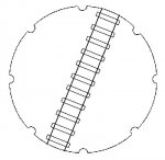
Encoder wheel with 29 slots on ungeared shaft on rear of gear motor
There are approximately 12,600 pulses per full revolution of actual turntable on geared shaft.
(Found using picaxe count command)
Using 1 pushbutton per input per rail stop spot for a total of 10 positions
or
I also have a keypad 4X3 rows pdf here http://www.robotshop.com/productinfo.aspx?pc=RB-Spa-203&lang=en-US

An axe022 project board and some 28x1’s
An ch30 project board or ch35 with 18x in them


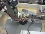
The mechanical side is done but can be changed
The electronics is done more or less using an ch30 project board without the second chip in it and direct wired to picaxe 18x outputs for pwm and highs and lows
My weak point is programing of course, I have got it to rotate both ways with pwm to l298 and figured out the count command enough to see it work.
But putting it all together is beyond me without at least a starting point in the picaxe basic.
So some help would be appreciated.

Thanks, Hugh
 

Adamey

Senior Member
This is how I'd do it (and suggestions/critiques are always welcome).

It would be nice to see a pic of your turntable and have the measurements. With 12,600 pulses for one revolution you have pretty good resolution and should be able to position fairly accurately just counting pulses.

As to the switches, I'd instead go with an optical sensor on each track position to indicate dead center as they are much faster and can be more accurate. I see two ways to do this.

The first is 10 different sensors going to 10 different inputs on the PICAXE (easiest, but not most efficient). Let's say you are at position 2 and want to go to position 4. You know you need to go 2,520 pulses (1,260 x 2). Start the motor in forward at a low PWM and increase PWM to simulate acceleration. Count pulses until you get close to 2,520 (say 2,300). Ignore the pulse that says you are at position 3 since we're not stopping there. Once you're close to position 4, reduce PWM to simulate deceleration so that the turntable is barely moving as you approach position 4. When the sensor for position 4 goes high, stop the motor and since the turntable is going so slow it should stop where you want.

The second method is a single optical sensor on your turntable with 10 "notches" cut out to represent dead center so we get a single pulse for each center position. We're again moving from position 2 to position 4. Start the motor in forward and again count pulses, slowing when getting close. When the optical sensor goes high, we again stop the motor (we also ignore the first pulse at position 3). This only requires a single sensor, but the problem is how to determine where the turntable currently is. We could place a single sensor at position 1 and rotate the turntable until we pass this position at which point we now have a reference. Problem with this is if we are a long way from position 1 then it could take awhile to "initialize". This could be reduced by having 2 or 3 sensors at various positions so the turntable moves less before it "finds" a "known" position. Or you could do it manually by looking where it is and entering that position on the keyboard the first time you power up the train.
 

Hughdh

New Member
Hi, Adamy

I like your answers but like you said 12,000 pulses should give me good enough accuracy.
I'm also thinking your right I need an start position, I can use an ir sensor for that and it will also help me get an exact count of pulses for 1 revolution.
I will take a pic of my turntable coble up :)


Regards, Hugh
 

boriz

Senior Member
How fast does the motor turn? (Frequency of encoder signal). If it's not too fast, this program might work. You may need to boost the Picaxe running speed.

Any slop or backlash in the gears will be a problem. You may need to build a spring 'detent' into the end of each receiver track. Like maybe a small wheel or ball bearing fixed to the end of a strip of springy metal, that pops/locates into a small hole/dent beneath each track position. Think how socket wrenches locate and hold the socket.

Question for technical...

On an M2 part, using two parallel processes, can one process monitor the word variable in a COUNT command that's running in another process? To facilitate an artificial timeout when count reaches a particular value. EG:

Code:
start0:
do
   count pin,65535,w0
loop
end

start1:
do
   if w0>500 then
      'exactly 500 pulses have been counted so far, even though the COUNT command has not yet timed out
   endif
loop
end
 
Last edited:

Adamey

Senior Member
hughdh: In re-reading your original post, it sounds like you used the COUNT command to determine there were 12,600 pulses per rotation, which suggests that you have already written some basic code and it worked OK. How long does it take to rotate the turntable? Do you know the speed of the motor?
 

Hughdh

New Member
Okay

It takes approx. 20 seconds for a full rotation of the turntable bridge, that's with the pwm set at pwmout 3,100,350
The motor itself is a 24Volt gear motor with 1-200 reduction and I'm using 12 volts instead of 24. I also have a further approx. 3-1 reduction on the final drive to the turntable itself.

Boriz: I don't know the freq. of the motor. but I have tried the count command( I used count 3, 15000, w1) and came up with approx. 12,000 counts per revolution

I'll see if I can figure a way to find the motor rpm.
Thanks, Hugh
 

boriz

Senior Member
200/1 * 3/1 = 600/1. Turntable turns at 3RPM, so motor shaft and encoder turn at 600 * 3 = 1800RPM. That's 30 revs per second, and with 29 slots on the disk, that's 870Hz. About 1.1mS per pulse.

The code I linked should just about manage that. If it doesn't, just run the Picaxe twice as fast.
 

boriz

Senior Member
Hmm. 29 pulses per motor shaft rotation @ 600/1 = 17400 pulses for one rev of the turntable, not 12600 like you said. Somethings not quite right methinks.
 

westaust55

Moderator
How are the 10 (rail) roads arranged?
1. All clustered together on one side such as at a round house and a single entry/exist line on the opposite side, or
2. All spread (equally or unequally) around the full 360 degrees?

Particularly if clustered, do you need to rotate through the full 360 degrees to be able to rotate a loco through 180 degrees.
Then the program logic may have to determine the shortest/fastest distance between to points (current and newlys elected).


What is the current draw of the stepper motor you are using?
I did some work (and posted on the forum) with an On Semiconductor Stepper controller chip capable of down to 1/16 step microstepping and being given commands via i2c to move to a specific position +/-32768 steps about a resetable xero point. The It has adjustable acceleration, running and holding currents.
But . . . is limited to 800 mA
 

Hughdh

New Member
Thanks Boriz

I went and counted the teeth on the final drive to the turn table its actually 1.7272 - 1
200/1 * 1.7272 /1 =345.44/1 after that you lost me I don't know were you got the 3 rpm from?

Hugh
 

boriz

Senior Member
345.44/1 is even better. That's about 1036RPM at the encoder and about 2mS per pulse. My code should be fast enough to catch that.

Code:
'Pseudocode
'designed for 8MHz. Important!

Motor on
do
   pulsin encoder_pin,1,word_variable
   inc position_counter
loop until position_counter>distance_to_travel or word_variable>25000
Motor off
PULSIN is usually used to measure the length of a pulse, but here it's used as just a fast way to wait for a pulse cycle. I have not tested it, but in theory it should be fast enough to catch all of your 2mS pulses. There may be some slight acceleration/deceleration issues that throw the count off a little bit. So experiment to find out how many pulses between tracks.

Also. If the track is jammed, stopping the pulses coming before Distance_to_travel is reached, then PULSIN will sit and wait for just over quarter of a second before exiting with Word_variable>25000. Sometimes the encoder will stop turning with the sensor obscured giving the same result. Shouldn't effect the utility though.
 
Last edited:

Hughdh

New Member
Hi Westaust55
I'm actually using a 200/1 gear motor with further gearing to 345.44/1. I thought about using steppers as I have a few laying around and also have micro stepping stepper drives but I've never been comfortable with steppers counting their steps accurately enough without feed back. Then again its just a small turntable not a mill or lathe.

I haven't set the turn table in place yet ( new layout still building) I imagine there will be a group of 5 around the round house and a few others here and there.
Regards, Hugh
 

techElder

Well-known member
Depending on your physical layout, I would think about using a 4-bit encoding scheme at each position. Sort of like a barcode.

In other words, apply an address to each position and read that address to determine where to stop. It would be trivial to know which direction to move from any one position.

You could add a 5th bit or some sort of analog "intensity window" to more precisely position the track at each stop once you got close to stopping.

Acceleration and deceleration could be controlled with the COUNT between stops.

Using COUNT exclusively might cause position "creep" over time. You need hardware to determine the precise position.
 

rossko57

Senior Member
I would agree that hardware over and above the "step" counter is necessary, but that could take the form of only a single "home" position indicator. Depends if you want a more software or hardware biased solution.

At start up, the program would need to rotate to find the home marker and zero the pseudo-step counter.
With a bit of cunning it can self-calibrate how many "steps" for a full rotate by spinning again. With a little more cunning, it can reset the zero each time it passes "home" to eliminate creep over time. (If the motor shaft "step" counter is not quite an integer relationship to the table, creep will happen).
Some experimentation should give you the "width" of the home marker in terms of motor "steps", so that an offset can be allowed for when turning the other way. But this too could self-calibrate.

The target positions for exit roads would need to be programmed in..... but
With yet more cunning and a couple of buttons, you could allow a manual teaching procedure, to set the position (and number?)of exit roads to be stored in EEPROM. This would allow for future layout changes or replicating for someone else.
 

boriz

Senior Member
I have been going about this the wrong way. I couldn't see the wood for the trees. It was your fancy encoder that put me off. How about KISS! Absolute repeatable precision with only a single robust component and using a single Picaxe input.

Remember what I said about a notch/detent and some sort of spring+roller for positive mechanical locating? How about a microswitch, the type that comes with a roller on the end:

micro.switch.jpg

This placed at the edge of the turntable disk, with the roller pressed against the edge so that the switch is always switched on. Until it hits a groove. The grooves are just the same size as the roller and it drops into it nicely, mechanically locating the turntable to a precise position and turning the microswitch off. The Picaxe just drives the motor until it detects the switch change state, then it stops. The notches in the turntable would look a bit like this:

turntable.jpg

(Not to scale)

It works equally well in both directions, CW and CCW, and couldn't be simpler. Also, you can place the notches anywhere, they don't have to be equidistant as shown in the image.
 

Hughdh

New Member
Hi
Yes there's a lot of ways to-do this I have done a lot of research and definitely like KISS.

Boriz I would use bumps instead and make them adjustable on an aluminium disk.

How about this - large hobby servo geared so as to get 360 deg or more and each button tells it to go to each position.
But are the accurate enough?

But like I said in my original post I can build and do the electrical but my Basic sucks and its hard to make the old brain put all the different parts of program together (pwm, button input, decoder input, counting and then telling it to go to a certain count position) ouch!

I could change to a stepper or geared stepper if anybody thinks that would be easier.

Thanks, Hugh
Boriz, In this case ignorance is not strength :eek:


2013-06-25 .jpg2013-06-25 2..jpg
 

boriz

Senior Member
Servo. Nah. They're geared for speed. Your turntable would whip around. And by the time you amplify the backlash by the diameter of the turntable, you'll never get it lined up twice in a row.

Stepper is a better idea, but still suspect. It can easily get out-of-step, usually corrected with an additional position sensor. You already have a perfectly good position sensor. Not sure what you'd gain.

If you insist on using the encoder, the only way you can be sure of precision is to never miss a pulse. That's non trivial and might require separating the sensor and drive aspects of this system into two Picaxes. And there's still the backlash to deal with, which would be negated using the above microswitch+detent system.

Perhaps they could be combined. Like maybe do a pulse countdown-to-target and slow the motor right down near it destination and wait for the microswitch to click before stopping the motor. Then you wouldn't need to be precise about the number of pulses. Just a ballpark figure would suffice to put the motor into slowly-look-for-detent mode.
 

Hughdh

New Member
What about moving sensor so it's on the turntable itself so there is only 10 counts per rev. and adding another switch or sensor for start position?
 

boriz

Senior Member
What about moving sensor so it's on the turntable itself so there is only 10 counts per rev. and adding another switch or sensor for start position?
Add a switch? Like maybe a microswitch? Then what do you need the optical sensor on the turntable for? Do you need a 'start position'? I guess I was assuming you just needed two buttons, one sends the table CW to the next position and the other CCW. Or maybe two presses to skip a position, or three to skip two etc..

As far as detecting the 10 line-up positions is concerned, optical or mechanical will work equally as well. But to make sure the tracks are dead aligned, you can't beat a mechanical detent. If you use a mechanical detent, then why not combine it with a switching action that can be detected by the microcontoller as suggested in post #17?

I'm having to make assumptions about how you want this to be operated. Maybe you could be more specific. Why would you need absolute position encoding?
 

Hughdh

New Member
Okay Yes I wanted to be able to press 1 of 10 momentary switches to goto specific track alignments

so I thought being able to count with encoder you could press say button 6 and the picaxe would know to goto count 2053 say and so on.
the extra switch or sensor would enable the picaxe to find start position whenever you turn the system on.

Jim: I put two sets of conductors in my slip rings so I could send the DCC signal for the rails on one set and 5 volts for an ir led pointing down through holes drilled in basin and receiver underneath.
 

boriz

Senior Member
I think I see my problem.

Generally, when I start planning a program, I think of the human interface first. What does the user want to see and do. I design the user interface first. Computer screen and keyboard, or LED and button.

As an engineer, you are probably looking at this from the opposite angle. Motor and lever first.

I'm sure we can meet in the middle :)
 

JimPerry

Senior Member
Had a thought :rolleyes: If you used a line of 4 photo gates under the turntable (on the baseboard) and 1 - 4 tabs at each position under the turntable you eliminate 10 microswitches and can sense upto 16 set positions with the 4-bit output from the sensor array.

This would allow you to reverse the motor from say 10 to 8 and forward from 10 to 3 reducing the rotation time. It could self align as a random non-aligned position would register as 0 and could move either way until it got a position signal :confused:
 

rossko57

Senior Member
Care needs to be taken with that sort of scheme, as not all the bits of the encoded position will change at exactly the same moment; potential for misreads of position code. Hardly insuperable, you might have one narrower tag as an "on station" indicator and the digit bits wider. That also allows for detection of "approaching station" and deaccelerating.
Physically it might be easier to implement as a disc with holes in.
Something needs to take account of different positioning depending on direction of rotation - back to precision counting or mechanical detents?

Personally I'd still look at software approach, with minimal fiddly switches/optos needing careful alignment under the baseboard.

Regarding the 'human interface', does the ten switches or whatever take account of which way round you want the bridge to end up, i.e. what (should) happen if you simply want to turn a locomotive?
 

Hughdh

New Member
Hi All

No I hadn't thought about which way it would go, I suppose it should go the least distance. I was was going to put in fwd and rev jog switches though.

I'm thinking about changing my drive system, even with the 345/1 reduction using this code below it isn't fine enough control with jog buttons.
So either more gearing or possibly stepper and or micro stepping.

init:
pwmout C.2, 50,225

main:

pwmout C.2, 50,225
pause 3000

goto main:
and just using push buttons to the enables on the L298

Hugh
 

rossko57

Senior Member
I'm thinking about changing my drive system, even with the 345/1 reduction using this code below it isn't fine enough control with jog buttons.
What is the problem, overrun by momentum, backlash in the geartrain? There are electronic means to tackle momentum e.g. motor braking, reducing speed approaching target. Prototypical too.
http://www.picaxeforum.co.uk/showthread.php?6784-Break-feature-on-an-L298
Repeatable, accurate positioning should avoid any need for jogging. You might be sold on the mechanical detent yet ;)
Turntables _look_ such a simple mechanism!
 

Hemi345

Senior Member
I haven't touched a model train in probably 30 years, but if memory serves me right, you'll have to power the rails on the table to move the locomotive off, right? So how do you make this connection? Or do you simply power the rails on the table separate from the rails that the locomotive will move to?

I'm thinking that if you can pwm the drive on the table slow enough, you could use your count method to get close, then slow the motor way down and use the PICAXE to power a rail on the table and sense this on the rail you want to match it up with. Once the connection is made, stop the motor.
 

Hughdh

New Member
What is the problem, overrun by momentum, backlash in the geartrain? There are electronic means to tackle momentum e.g. motor braking, reducing speed approaching target. Prototypical too.
http://www.picaxeforum.co.uk/showthread.php?6784-Break-feature-on-an-L298
Repeatable, accurate positioning should avoid any need for jogging. You might be sold on the mechanical detent yet ;)
Turntables _look_ such a simple mechanism!
Hi rossko
none of the above.
Mostly it being a DC motor it has to run at minimum rpm and at that speed and I just touch one of the push buttons it still moves about half an inch on the outside dia. of 13.5 inches.

So I would never be able to even jog it into position.
Hugh
 

bfgstew

Senior Member
I am just a minor amateur,
but why do professionals use

things like

http://www.axminster.co.uk/axminster-indexing-plates-for-rotary-tables-prod459455/


e
Oooooh, a blast from the past, not used one of those since I was an apprentice, dividing heads we called them.

With a 1.8 deg stepper you are looking at approx. 5.5mm travel / step if your turntable is 13.5" dia, with a 0.9 deg stepper that will be reduced by half so approx. 2.75mm travel / step. That is if directly driven straight off the motor shaft, gear reduction can reduce that down anything you want, and speed wise, can be controlled accurately in the code, giving an authentic motion to the table.
With a stepper you can code in the steps for each location fairly accurately, but how about incorporating as Boriz has said, some sort of detent, a spring loaded ball and socket so as the table comes to each station the stepper positions it , the detent locates it?
 
Last edited:

Adamey

Senior Member
Some good ideas in this thread. A detent is great to allow you to make sure the tracks line up perfectly. When using a detent I think it's preferable to have some play (lash) in the gears so that when you stop the motor the turntable is free to move back and forth a small amount allowing the detent to center the track without putting tension on the gears.

I was thinking you could attach a solenoid to the detent mechanism (whatever you choose) such that when energized it removes the tension from the detent. This way you don't get unrealistic "jumps" when the turntable is passing by the detents of tracks you don't want on its way to the position you do want. You de-energize the solenoid right when you stop the motor to "lock" the track in the right position.

You mentioned you're just getting into writing code. Here's a simple bit of code to get you started.

Code:
symbol Clockwise = 1
symbol Counterclockwise = 0
symbol CurrentPos = b0
symbol RequestedPos = b1
symbol TurntableDistance = b2
symbol TurntableDirection = b3

main:

CurrentPos = 9
RequestedPos = 2

gosub GetDistanceDirection
end


GetDistanceDirection:
	TurntableDistance = CurrentPos MAX RequestedPos			; get absolute value
	TurntableDistance = CurrentPos MIN RequestedPos - TurntableDistance
	TurntableDirection = Clockwise
	
	if TurntableDistance > 5 then
		TurntableDistance = 10 - TurntableDistance		; shortest distance
		if CurrentPos < RequestedPos then
			TurntableDirection = Counterclockwise
		endif
	elseif CurrentPos > RequestedPos then
			TurntableDirection = Counterclockwise
	endif
return
You have your current position and requested position. The code will determine how many steps to travel to get to the requested position, which direction the turntable needs to go and takes the shortest route (for example, going from 2>9 will return counterclockwise for direction and 3 for distance). I simulated it and it works fine.
 

Adamey

Senior Member
Hi rossko
none of the above.
Mostly it being a DC motor it has to run at minimum rpm and at that speed and I just touch one of the push buttons it still moves about half an inch on the outside dia. of 13.5 inches.

So I would never be able to even jog it into position.
Hugh
Is that one push of a button to your PICAXE running your test program or is that one quick push of a button directly powering up the motor itself? What I'm trying to get at is have you tried to send a really short pulse to the motor to see how far it goes? Forget about PWM for now, just try making the pin controlling your motor high for a specific time (say 100ms, 200ms and so on) to see how far it moves.
 

Paix

Senior Member
Hmmmmm. Interesting about the overrun and of course the proposed control of pulsing as a possible solution to it.

I take it in all this that the polarity of the rails, assuming that they are DC powered, has been fully considered - but this is a digression, so rhetorical and not for discussion in this thread.
 

rossko57

Senior Member
Mostly it being a DC motor it has to run at minimum rpm and at that speed and I just touch one of the push buttons it still moves about half an inch on the outside dia. of 13.5 inches.
This is where the pulsing/PWM comes in ... delivering full-power pulses to get the motor moving, but very brief pulses so that average energy (speed) is low. The locomotive motors are driven in this fashion for low-speed controllability. Computer control of the turntable motor would allow you to ramp power/speed up and down in the same way as the trains.
 
Top