mildenhall
New Member
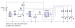
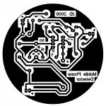
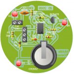
This is a mobile phone sensor I build for my Y8s (12-13 year olds). It fits nicely onto a circular PCB.
The BC547 does most of the work, and the PIC is just used to control the sensitivity, and how the circuit responds to being triggered.
Before you ask, I desided the 3.5mm jack socket was too complicated for Y8s to solder, so used a tripple terminal block instead.
The BC547 does most of the work, and the PIC is just used to control the sensitivity, and how the circuit responds to being triggered.
Before you ask, I desided the 3.5mm jack socket was too complicated for Y8s to solder, so used a tripple terminal block instead.
Code:
'*** Mobile Phone Detector
'*** (c) Jerry Davis, 2009
'*** King Edward VII Technoloy College
'*** Melton Mowbray, LE13 1DR, UK

'#define SHOWDEBUG					'comment out to stop the debug screen

symbol ANALOGUE_DATUM = 65			'preset analogue datum value
symbol DIFFERENCE_TRIGGER = 30		'value above datum that will cause a trigger

							'depending on the phone make, model and environment
							'the above two vlaues may need to be modified to suit

main:
	readadc 1, b1				'read current analoue value

	if b1 > ANALOGUE_DATUM then		'if b1 is greater than b0...
		b2 = b1 - ANALOGUE_DATUM	'subtract b0 from b1 and store the difference in b2
	else
		b2 = 0				'otherwise b2 = 0 to stop it going negative
	endif

#ifdef SHOWDEBUG
	debug
#endif

	if b2 > DIFFERENCE_TRIGGER then	'if the analogue difference is greater than 27
		for b4 = 0 to 9
			high 0
			pause 200
			low 0
			high 2
			pause 200
			low 2
			high 4
			pause 200
			low 4
		next b4
	endif

#ifndef SHOWDEBUG
	nap 0						'power save nap
#endif						'when debugging, nap slows the program
							'so the #ifndef removes it if debugging

	goto main
Attachments
-
 39.8 KB Views: 427
Last edited:
") .
.