I decided to refresh my toner transfer skills with a mixture of through hole and smd parts. For lack of anything better, the circuit is a basic non-inverted USB serial interface to a Picaxe 08/08m2; nothing new here. The pins are brought out to Arduino style stackable headers. These headers allow some space on the bottom together with enough depth to plug into a breadboard. The board is single sided with the socketed Pixaxe, an LED and a two pin shunt on/off switch for hard reset on the top. The inputs are TX, Rx, Gnd, and 3v3/5V.This is the basic 22k/10K download circuit with inversion performed by a TI 74LVC2G14 that has a DBV footprint(SOT-23-6). The discretes are 0805 form factor and yes, the Picaxe has a 0.1uF ceramic decoupling capacitor. The traces are 10 mils and the IC footprints have a dot on the board to mark pin 1. Other copper text denotes pin numbers, etc.
The board was directly routed as an Eagle Cad Brd with out any preliminary schematic. In order to get the surface mount parts on the bottom copper layer, it is necessary to mirror after placement and then rotate the ICs to get the orientation you want. The PDF and an annotated PDF together with the Eagle Brd file are attached.
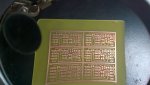
The PDF was printed directly (no mirroring) to Hp Presentation paper on a HP1102W laser printer set to the maximum print density(5). The image was then placed face down and taped to a cleaned, single sided, 0.032 copperclad FR4 piece of stock. This was then passed through a laminator set at 160 deg C. Twelve passes were used; rotating the board 90 deg each pass. The paper was then released by soaking the laminated board with some warm water and dishwashing detergent. The board was then etched with the "Edinburgh" version of ferric chloride. I use a plastic sandwich container with about 1/2 inch of etchant and help the process along with gentle rubbing using a piece of microfiber cloth (wear gloves). After etching, the toner was removed with acetone. With magnification, a tiny amount of pitting can be observed. I normally use Pulsar Green Foil to seal the toner before etching, but didn't this time. All told, excluding the Eagle layout time, the board in the image took about 30 min. I use a 4" diamond tile saw to cut the FR4.
This is also an experiment in soldering SMT parts to a board that is not solder masked. My gut feel is that it is not going to be pretty with solder running off the smd pad to attached traces. I have some dry film solder mask, but to use it the laminating process has to be repeated. And additionally, the pads imaged, then UV exposed, then developed, then post UV hardened and baked. This is hardly worth it for one-off projects and basically more that doubles the time to make a board.
I don't think there are any glitches in the circuit, but no guarantees ...
Baxter
The board was directly routed as an Eagle Cad Brd with out any preliminary schematic. In order to get the surface mount parts on the bottom copper layer, it is necessary to mirror after placement and then rotate the ICs to get the orientation you want. The PDF and an annotated PDF together with the Eagle Brd file are attached.
The PDF was printed directly (no mirroring) to Hp Presentation paper on a HP1102W laser printer set to the maximum print density(5). The image was then placed face down and taped to a cleaned, single sided, 0.032 copperclad FR4 piece of stock. This was then passed through a laminator set at 160 deg C. Twelve passes were used; rotating the board 90 deg each pass. The paper was then released by soaking the laminated board with some warm water and dishwashing detergent. The board was then etched with the "Edinburgh" version of ferric chloride. I use a plastic sandwich container with about 1/2 inch of etchant and help the process along with gentle rubbing using a piece of microfiber cloth (wear gloves). After etching, the toner was removed with acetone. With magnification, a tiny amount of pitting can be observed. I normally use Pulsar Green Foil to seal the toner before etching, but didn't this time. All told, excluding the Eagle layout time, the board in the image took about 30 min. I use a 4" diamond tile saw to cut the FR4.
This is also an experiment in soldering SMT parts to a board that is not solder masked. My gut feel is that it is not going to be pretty with solder running off the smd pad to attached traces. I have some dry film solder mask, but to use it the laminating process has to be repeated. And additionally, the pads imaged, then UV exposed, then developed, then post UV hardened and baked. This is hardly worth it for one-off projects and basically more that doubles the time to make a board.
I don't think there are any glitches in the circuit, but no guarantees ...
Baxter
Attachments
-
61.8 KB Views: 10
-
 138.3 KB Views: 38