Mini 08M Prototype board

Marcwolf

Senior Member
Hi Folks
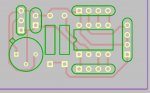
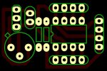
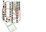
I have been working quietly in the background with a few projects. One of the things I needed was a very small 08M Prototyping board.

So - here is the Diptrace file of it. Please rename from CAD to RAR

For size contraint I tend to use 4 molex pins for the programming which consumes far less space than a stereo socket
I also have included on the board space for an optional 5V regulator.

All pins on the 08M are accessable

Hope someone find this useful

Dave
 

Attachments

Andrew Cowan

Senior Member
Here you go Martin - rename it to .dip.

Dave - there's enough room to make the tracks and pads a bit bigger - this makes it easier to etch, drill, solder and makes the board more durable.

A
 

Attachments

Last edited:

Dippy

Moderator
Gee, you Diptrace clique like keeping a secret :)

Can't we have JPG so us normal people can see it?
 

Dippy

Moderator
That's a very nice 'My First PCB'. Well done.

I agree with Andrew; make the pads and tracks bigger.
On the chip you could even do round-ended-finger pads. (The almost-oval looking pad style).

If you re-use etchant then filling blank areas will cut down on chemical usage too - as there is less copper to remove. The downside is printer ink/toner usage.

For home-brew I would ALWAYS recommend to set the drill size down.
It gives more meat on the pad and, lets face it, you can use whatever drill bit you want.
And also a small plotted hole e.g. 0.5mm will allow the drill to centre better for hand drilling.
 

Andrew Cowan

Senior Member
See the attached picture for 'beefed up' version. Should be much easier to make/solder.

I also made the resistors a bit smaller to make the board more compact.

A
 

Attachments

Marcwolf

Senior Member
Hi Andrew and Dippy

Many thanks for the advice.

I will have to look into the 'hole size' issue, This board took me about and hour to work out with DipTrace.

Can you tell me where I can set the hole size and how to set up oval pads.

I do agree with Dippy re the size of the pads etc but I do not know where to find the information

Many thanks for your advice and comments

Dave

p.s.
I am adding a new board I have made. Yes I have thin traces but my photo/etching handles that fine.

The board is an 18X that uses a ULN 2003 to power some high intensity LEDs. The MOSFET is so I can use the PWN to vary brightness

Ad some of you are aware I make special effects/costumes as a hobby. This will go into my suit so I can control the eye LED's. There are 2 Red, 2 Green, and I want to make the system Blink, Wink, and Glare (Red LEDs on full power)
 

Attachments

Last edited:

MartinM57

Moderator
Right Mouse Button on the trace and select Line Width, Trace Width or Net Width as required and then select the required width - default choices are 0.25mm, 0.4mm, 0.5mm or 1mm plus a custom setting to use whatever you want.
 

Andrew Cowan

Senior Member
0.5mm should be the thinnest used for a basic board - then use .8 or 1mm tracks where they fit. You can make part of the track thicker by right clicking and selecting Line Width rather than Track Width.

A
 

Wrenow

Senior Member
p.s.
I am adding a new board I have made. Yes I have thin traces but my photo/etching handles that fine.

The board is an 18X that uses a ULN 2003 to power some high intensity LEDs. The MOSFET is so I can use the PWN to vary brightness

Ad some of you are aware I make special effects/costumes as a hobby. This will go into my suit so I can control the eye LED's. There are 2 Red, 2 Green, and I want to make the system Blink, Wink, and Glare (Red LEDs on full power)

Hmmm, when making costuming eyes, I have used tricolor LEDs (set behind appropriate "not too dense" sunglass lenses (or, for a really "dead eyed" look, some black netting. I have not taken the step of Picaxing them yet - great idea!

Anyway these LEDs have 3 leads, one is common, one is red, the other is green. Red and green turned on on together is yellow. I had just set it up to two micro switches in my glove, so that when I bent one or both of two designated fingers, the LED color chosen would light. I was able to cycle the coulurs pretty quickly.

Cheers,

Wreno
 

Marcwolf

Senior Member
Hi Wrenow

Tri color LED are nice however they do not have much in the way of brightness. When walking around in full daylight (and I am in Brisbane Aust and we have a LOT of sun) one nees a reasonable brightness to be seen.

Originally I had a pair of 3mm 6000mCP green LED's behind the lense and that was quite visible - but wiring it was problematic re very tiny wires.

My current idea is to use fibre optic cable that can be heated and bent to do the same purpose. the LED's are in the 10,000mCP range so I will use PWM to adjust their brightness to suit conditions or emotional responses.

Will keep folks posted.

Dave
 
Top