Measuring RPM pulses

Steevo25

New Member
Hi All,

I have been playing around with PICAXE for a few years but only for fun. Now I have a more serious project to complete but not sure where to start with the code.

Firstly, I am not an electronic expert and play around for pleasure and learning. I know a bit more than a beginner but still have a long way to go. I am ok with most electronic components and know how most work and operate but only to a basic level.

Now on to the project. I currently own an aircraft. Earlier this year I installed an electronic flight information system (EFIS) in to it. For anyone that doesn't know, the EFIS displays a variety of flight parameters to me such as speed, height, oil temperature and pressure and navigation information. Another item it will display is engine RPM. Unfortunately it will not display the RPM on my engine due to the following reason.

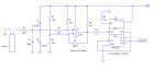
The RPM is detected by a Hall effect sensor which counts the teeth on the flywheel. Every time a flywheel tooth passes the sensor, the sensor creates a pulse. The flywheel has 60 teeth so 60 pulses equals 1 revolution of the engine. The EFIS cannot cope with that number of pulses with about 6 pulses per revolution being the maximum. The EFIS has a configuration item in its menu for the number of pulses per revolution.

I need to design a circuit that will read the pulses from the Hall effect sensor and then send about 4 pulses per revolution out of an output pin to the EFIS. This basically means that when 15 pulses have been read from the Hall effect sensor, it sends a pulse to the EFIS and then another output pulse after the next 15 pulses read from the sensor and so on.

This is where I am lost. I am fine creating the circuit to do this but have no idea what code to write to do it. Bearing in mind that the engine has the potential to run at 3300 RPM, there cannot be much delay in sending output pulses considering that the Hall effect sensor could be creating 3300 pulses per second maximum.

I would really appreciate if someone could advise me on the PICAXE code required to do this. I had a look in the manual at the PULSIN and PULSOUT commands but they really didn't make much sense to me as I have never had to deal with pulses before.

Many thanks in advance.

Steve
 

SAborn

Senior Member
This is one application i think i would not use a picaxe for, and do it in hardware chips, like 2 x 4017 decade counter chips, and simply take the output signal off a pin that was after a 10 count or 15 count as you requested.
 

Bill.b

Senior Member
Have you concidered using a frequency divider. ie cmos 4017 as a divide by 10 counter, this would be simple and give you the 6 pulses per rev you require.

The 'count' command in picaxe could be use but I feel you would miss pulses due to program timing.

Bill
 

hippy

Technical Support
Staff member
The flywheel has 60 teeth so 60 pulses equals 1 revolution of the engine. The EFIS cannot cope with that number of pulses with about 6 pulses per revolution being the maximum. The EFIS has a configuration item in its menu for the number of pulses per revolution.
Creating a hardware 'divide by 10' should be easy with a 4017 decade counter, and there are likely alternatives. You can probably have the problem solved in the time it takes to even think how best to do it with a PICAXE.

Using a PICAXE I would probably just poll the input and bit-bang out the pulse, run as fast as possible. This is for your proposed 'divide by 15' ...

Code:
#Picaxe 08M2

Symbol IN  = pinC.3
Symbol OUT =    C.1

PowerOnReset:
  Low OUT
  SetFreq M32

Main:
  Pulse01: Do : Loop Until IN = 0 : Do : Loop Until IN = 1
  Pulse02: Do : Loop Until IN = 0 : Do : Loop Until IN = 1
  Pulse03: Do : Loop Until IN = 0 : Do : Loop Until IN = 1
  Pulse04: Do : Loop Until IN = 0 : Do : Loop Until IN = 1
  Pulse05: Do : Loop Until IN = 0 : Do : Loop Until IN = 1
  Pulse06: Do : Loop Until IN = 0 : Do : Loop Until IN = 1
  Pulse07: Do : Loop Until IN = 0 : Do : Loop Until IN = 1
  High OUT
  Pulse08: Do : Loop Until IN = 0 : Do : Loop Until IN = 1
  Pulse09: Do : Loop Until IN = 0 : Do : Loop Until IN = 1
  Pulse10: Do : Loop Until IN = 0 : Do : Loop Until IN = 1
  Pulse11: Do : Loop Until IN = 0 : Do : Loop Until IN = 1
  Pulse12: Do : Loop Until IN = 0 : Do : Loop Until IN = 1
  Pulse13: Do : Loop Until IN = 0 : Do : Loop Until IN = 1
  Pulse14: Do : Loop Until IN = 0 : Do : Loop Until IN = 1
  Low OUT
  Pulse15: Do : Loop Until IN = 0 : Do : Loop Until IN = 1
  Goto Main
It doesn't really matter where the main loop HIGH and LOW go but they are placed where they are to minimise time between 'PulseXX:' labels.

A 'divide by 10' is even simpler ...

Code:
#Picaxe 08M2

Symbol IN  = pinC.3
Symbol OUT =    C.1

PowerOnReset:
  Low OUT
  SetFreq M32

Main:
  Pulse01: Do : Loop Until IN = 0 : Do : Loop Until IN = 1
  Pulse02: Do : Loop Until IN = 0 : Do : Loop Until IN = 1
  Pulse03: Do : Loop Until IN = 0 : Do : Loop Until IN = 1
  Pulse04: Do : Loop Until IN = 0 : Do : Loop Until IN = 1
  Toggle OUT
  Pulse05: Do : Loop Until IN = 0 : Do : Loop Until IN = 1
  Goto Main
 

Buzby

Senior Member
What about using the PICAXE counter, available on X2 ( except 20X2 ), in external count mode ?.
 

Goeytex

Senior Member
At 3300 RPM there will be 3300 pulses per second given a 60 tooth gear.
That is a 3.3KHz signal. Assuming a 50% duty that's ~150us on and 150us off.
The Picaxe will need to do all of its processing between each edge or it will miss pulses.
150us might be cutting it close on an M2 part @32 MHz. Test the code and see. It may work fine.
You will probably need a scope or logic analyzer to check for missed pulses.

IF there are missed pulses then there are other options, one being a 20X2 operating at 64 MHz.

Another might be to use something like a 74HC390 to first divide the signal by 5 then let the Picaxe do the divide by 3.
In this case, taking the signal at the 74HC390-Q3 output, the space between pulses will be ~ 1.2ms. More than enough
to process the loops with time to spare.
 

geoff07

Senior Member
If you can use a different sensor, a reflective optical sensor and a white stripe would create a one-pulse-per-rev signal. That would easily be within the capacity of a picaxe.
 

rossko57

Senior Member
I would think carefully about using optical sensors in an oily engine bay, there are reasons why the original setup is magnetic. On the other hand it could be feasible to use opto sensing of the prop.
In an aircraft situation, there may be regulatory reasons not to add extra uncertified equipment.

I think I'd be looking for an alternative RPM signal - maybe derived from ignition pulses.
 

SAborn

Senior Member
In an aircraft situation, there may be regulatory reasons not to add extra uncertified equipment.
I was waiting for the Ohhh Aircraft standards to pop up.

One would expect any RPM reading would be better than non at all.

Simplicity and reliability is why i and others have suggested using a hardware solution with 4017 decade counters, as they have up to 15 volt input/supply, (perhaps no voltage control required), being a dedicated chip there is no program required or program to become corrupted.

As Hippy said..... it will take less time to construct the circuit than write a program to suit.
 

RexLan

Senior Member
I was waiting for the Ohhh Aircraft standards to pop up.

One would expect any RPM reading would be better than non at all.

Simplicity and reliability is why i and others have suggested using a hardware solution with 4017 decade counters, as they have up to 15 volt input/supply, (perhaps no voltage control required), being a dedicated chip there is no program required or program to become corrupted.

As Hippy said..... it will take less time to construct the circuit than write a program to suit.
I agree and the hardware solution would be much more reliable. I am confident there are alternative RPM signal pick up points available as well, most likely from the ignition.

The Aircraft is most likely experimental or homebuilt and I doubt the introduction of any parts is an issue.
 

crowland

Member
The OP seems to be in the UK and AFAIK there isn't a concept of experimental like there is in the USA.

Speaking as a pilot an instrument that is reading incorrectly is worse than not having one. There can be a fatal tendency to believe the instrument until it's too late.

I guess that this is being seen as a secondary instrument and that there's a certified RPM indicator as well. If the EFIS controls the engine in some way then this could be a problem.

Chris
 

hippy

Technical Support
Staff member
Testing the code in post #4; it misses some pulses at 3300 per second, and would possibly not work at all if the pulses were shorter than 50% duty. That is likely to be the case with a hall effect sensor, and even running at 64MHz won't solve that problem. I had forgotten about that practical issue earlier!

One could add a pulse stretcher and run at 64MHz, a flip-flop to give 50% duty and half the rate of pulses to a PICAXE, or perhaps even configure an internal counter to be a hardware or software assisted divider but the simple, easiest and probably best solution is a hardware divider.
 

Steevo25

New Member
Many thanks to all of you. I hadn't considered a decade counter but after reading up on it, it does seem a very good option so will be ordering a couple to try out. I will still try a picaxe as well just for my own learning. The code given makes it look so easy.

I am going to put my oscilloscope on there first as I have no idea of voltages yet. I suspect 12v so would have to clamp that voltage for the picaxe I assume. The data sheet for the decade counter says it handles up to 15v.

There are other places to connect the EFIS such as coil or the stator but they are not clean and do have other side effects. The reason I need to do this is that the stator is being upgraded to a proper alternator so all I have is the flywheel tooth sensor as a reliable source.

My aircraft is a permit aircraft so anything I do I simply just have to get signed off by an inspector. RPM is not a crucial component to actually fly as such so they will just be looking at fire risk and properly fused etc.

Would a decade counter handle up to 3300 pulses per second?
 

Steevo25

New Member
Just got round to starting this mini project. I put an oscilloscope on the aircraft just to see what currently comes out. One mistake I made is that there are actually 101 teeth on the flywheel not 60 so the 4017 seems the best course of action because my EFIS will got up to 10 (or 10.1 in this case with the 4017).

From the oscilloscope, the magnetic sensor is obviously producing AC current. As the RPM increases the output voltage also increases. At low RPM, the sensor seems to only generate a few millivolts. At max RPM it seems to go up to about 4v.

Does any one know what the minimum clock voltage is for the 4017. I cannot quite work out the datasheet (my inexperience not that the datasheets are rubbish). Will just a few millivolts be enough to trigger the 4017 clock?
 

Goeytex

Senior Member
Millivolts will not trigger the 4017

The min input level depends upon the supply voltage. Here is a chart for reference it shows the typical input threshold @ 25c

VCC = 2.0 High = 1.2
VCC = 4.5 High = 2.4
VCC = 6.0 High = 3.2

It may be less complicated to take the signal from somewhere other than the direct output of the magnetic sensor. Seems to me that this may be a reluctance type sensor and not a hall effect sensor.
 

Dippy

Moderator
Steev, can you clarify...

You say "AC current" and then give us voltage values....(?).
Then mention clocks...

We have AC current, voltages (DC or ACrms/peak?) and digital.
Does this mean the output is an AC voltage where the frequency AND voltage varies?
Have you put this AC current into a load resistor in order to get the voltage?
If you are down to millivolts then you will need to do more before you start using logic chips.

Is it really a Hall sensor? What type?
It's all a bit confusing and needs more detail.
Let's get the sensor signal sorted before going any further.
 

Goeytex

Senior Member
The existing sensor is already sending its signal "somewhere" (ECU ?) where it is being conditioned into pulses that are readable by logic chips or an MCU. It is then further processed to produce ignition pulses and fuel injector pulses. (Assuming a modern engine).

Why not locate the (already conditioned) ignition control signal for one of the ignition coils and use that signal? Whether or not this will work depends upon the specified requirements of the EFIS tachometer signal.

I would be tempted to trace the signal from the sensor to the ECU and then tap off a good clean signal from a point inside the ECU.
 

SAborn

Senior Member
I would not tap into the ECU sensor and would do the path of the flywheel sensor.

As Dippy says the sensor information is a little unclear, my guess is its a induction sensor and not a hall sensor as originally suggested.

It could be a linear hall sensor, but not likely for a pulse count application.

The question is ........ is it a pulsed DC signal, or an AC signal from the sensor.
 

Goeytex

Senior Member
The ECU may even have a "tach out" signal available. We need more info from the OP before sending the him on wild goose chases or having him build a complicated circuit to produce a signal that may already exist.
 

Steevo25

New Member
Very sorry all, I should have gathered all the information before posting. I just got the initial information off the EFIS forum and took that as verbatim.

Now I have properly investigated it and seen for myself, I know now what is going on.

First of all the engine does not have an ECU. It is an extremely basic engine, no fuel injection, no nothing, just a carb.

The sensor is actually a magnetic pickup sensor. It requires no power to operate and simply has 2 wires coming out of it. A red wire and a black wire. The sensor tip sits about 11 thousands of an inch away from the flywheel and everytime a flywheel tooth passes the sensor it causes the sensor to generate a pulse. The sensor would normally connect directly to an analogue RPM gauge. This gauge was removed when the EFIS system was installed. Currently I am powering the RPM display from the alternator (basically a stator/dynamo). The stator is also being removed as it doesn't produce enough power to run the electrics on the aircraft properly and also does not start charging until about 1500RPM so when you are at very low RPM, the electrics are just running purely from the battery and the charge in the battery does not start to get replaced until you reach 1500RPM. This is being replaced by an alternator which is virtually identical to that found in a standard car. Once it is replaced, I will not be able to power the RPM input on the EFIS anymore as the new alternator just produces a rectified DC charge at just below 14volts whereas the stator produces AC current based on magnets on the back of the flywheel (4 pulses per RPM going from +20v to -20v).

Using the oscilloscope on the sensor I plugged the ground of the oscilloscope to the black wire and the probe to the red wire. When I spin the propellor by hand (it wouldn't really run this slow in real life) it produces just a few millivolts. With the engine running at idle (around 700RPM) the oscilloscope pulses between +1.5v and -1.5v. Increasing the power to full power (around 3100RPM) the oscilloscope was showing pulses from around +4v to -4v.

The EFIS doesn't really care what type of pulse it is getting, it just counts a pulse as a high going to low. The current stator reading goes from about +20v to -20v but the EFIS will accept much lower voltages than that for a pulse. The EFIS allows me to configure how many pulses there are to 1RPM (in this case if I was using a decade counter the figure would be 10.1 because there are 101 teeth on the flywheel). But the EFIS has many tasks to carry out and cannot handle 101 pulses per RPM, so plugging the magnetic pickup sensor in to it just really gives a random reading on the display, nothing like the correct RPM.

I hope this makes a bit more sense as to how the system works.
 

Goeytex

Senior Member
A lot more sense.

So all you really need is a simple front end /signal booster for the signal and a decade counter after that. A Picaxe is not needed at all.
 

Steevo25

New Member
It seems that is the case. Are there any suggestions on something to use to boost the signal from the magnetic pickup sensor in to an acceptable value for the decade counter?
 

MartinM57

Moderator
The sensor is actually a magnetic pickup sensor...
Is it a VR (variable reluctance) sensor? It certainly sounds like it, as the voltage increases with rpm

If so, a common chip for "boost the signal from the magnetic pickup sensor in to an acceptable value for the decade counter" is a National Semiconductor LM1815N which is a "zero crossing detector" chip for VR sensors that only needs a small voltage input (crossing zero, obviously) to create a solid digital output.

I've tried one in the past and it works just fine.

You can find its data sheet by googling "LM1815N" - I picked it up from within another site (related to diy EFI), so not appropriate to post the link here (but for me, it was the 7th one in the Google hit list :))
 

Goeytex

Senior Member
Here is a proposed circuit. It will boost the voltage to 5.0v out, and will work with relatively noisy signals. The Comparator is used as a zero cross detector. I have not built this exact circuit but have used similar circuits in the past with excellent results. It simulates fine in PSPICE.

The schematic shows an LM339 Comparator, but an LM393 dual comparator will work exactly the same. I did not have a model for the 393.
The comparator output can go to any DIV/10 IC, so a 74HC4017 will also work fine.

Good luck.
 

Attachments

rossko57

Senior Member
If you haven't yet sourced an alternator, some types are available with an "RPM" output. (basically a tap off one AC phase)
 

Steevo25

New Member
It would be really nice if I could use any alternator but unfortunately I have to use a special kit that has all the conversions to fit my aircraft.
 

mpgmike

New Member
The higher end X chips have the ability to SETTIMER COUNT preload. Overflow occurs at 65536, so a pre-load of 65515 would give you an overflow every 25 pulses (4X/rev). Set the interrupt to occur on timer overflow; SETINTFLAGS %10000000. Create a subroutine that pulses out on the overflow (don't forget to clear the flag and turn the interrupt back on). Feed your PICAXE the output from the comparator. (On a side note, for aircraft you should use an LM193 instead of the LM393, as temperature range is dramatically extended). Perhaps this can get you started.

Mike
 
Top