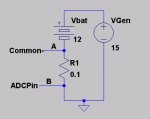
I’m trying to measure current using the voltage drop across a resistor. It’s basically a battery charger. The simplified circuit is attached. “A” is common "–" between picaxe and battery. I need to measure the voltage drop across A and B, but B is more negative than A. Any idea how I can change this to a positive voltage I can measure with an ADC pin?
Any help appreciated.
Any help appreciated.
Attachments
-
 10.5 KB Views: 99
")