Measuring Current with PICAXE - between 20 and 40 Amps DC? - even possible?

Blazemaguire

Senior Member
Hi,

At my school we're entering our 2nd year of the 'green power electric car' race series.

We'd like to get even more efficient this year and start to measure the current draw of our car, ideally logging it while testing different gear ratios and bodywork designs.

I know you can do data logging with a PIC fairly easily, but how easy would it be to measure and log current draw (at a hefty 20 - 40 amps DC)? - The ideal current draw for the motor we have to use in the race is around 24Amps continuous (as in 24A allows you to 'just finish' but do the highest speed and therefore most laps in a 4 hour endurance race) - The current can climb a lot higher during initial acceleration until the motor is up to its most efficient RPM (I know this from research of other teams not our car!).

Am i flogging a dead horse trying to do this with a PIC? - Should I just invest in a nice digital ammeter off ebay with a shunt? (going to cost about £25+ the long delay for it to arrive from China)

If it's possible, I think it would be a nice project for our greenpower students to do, and if they cannot find time one of my A-level systems and control students could pick it up as an A2 project idea

Unfortunatly I do not know how you would safely interface and measure the current with a PIC being that you have to measure current in series? (unless using hall effect method I gather?)

Any ideas from you fine chaps?

Rob
 

eddydde

Member
Very easy to do with a picaxe! Google for ADC712 current measuring device.
I have three of them running off a picaxe 20X2.
Use ADC inputs on picaxe and I am using a LCD display.
i can pm you info if you like.
 

Jeremy Harris

Senior Member
Easy enough to do. Ideally I'd go for a Hall effect current sensor, something like the Allegro ACS range or maybe one of the LEM ones. These are easy to interface to the Picaxe as they output a DC voltage that is proportional to current, isolated from the current being measured, and which can be read directly by the ADC in the Picaxe.
 

Blazemaguire

Senior Member
Right... I'm maybe being a bit thick here... I assume the 30A version will only measure + or - 30A? (where our current may spike at 45Amps and rapidly drop to between 20 and 30Amps) - Will it measure higher than this (albeit with less accuracy?)

Which version are you using Eddy? what current ranges are you measuring?
 

Blazemaguire

Senior Member
O.k I've done a bit of further research and it appears they do a 50Amp version (and also 100, 150, 200amp versions for anyone doing something mental!)

ACS758LCB-050B-PFF-T is the RS part number for the 50amp version - £5.00 a chip, but my dad will order that courtesy of a large british based defense company who shall go unnamed...
 

Dippy

Moderator
That looks OK (I used the same one in a Motor drive) and LEM is a good choice also.
We used LEM in a not-so-large automotive company who will remain nameless.
And I'm using LEM again in a motor drive test machine design I'm doing currently (haha , no pun intended).

Will you be adding a little filtering to attenuate spikes?
How will you be connecting the conductor to the tabs?

By the way, if it's British it will be a defence Company :)

Mmmm ... will my taxes be paying for your project? :rolleyes:
 

Blazemaguire

Senior Member
That looks OK (I used the same one in a Motor drive) and LEM is a good choice also.
We used LEM in a not-so-large automotive company who will remain nameless.
And I'm using LEM again in a motor drive test machine design I'm doing currently (haha , no pun intended).

Will you be adding a little filtering to attenuate spikes?
How will you be connecting the conductor to the tabs?

By the way, if it's British it will be a defence Company :)

Mmmm ... will my taxes be paying for your project? :rolleyes:

hey! - I'm a technology teacher... not an English teacher, in my defenCe.

And my taxes will be paying as well....

I would welcome your thoughts on how to connect to the motor circuit - I'm assuming (from the website info I can find) that you need a copper bus bar in line with the main motor cable to attach the chip to? - does it just 'rest' on the copper? - is it soldered? does it need thermal grease compound?

As for protecting against spikes this is beyond my experience - I thought the whole idea is that it was isolated? - what would you suggest?
 

Jeremy Harris

Senior Member
They are fully isolated, so no worry about spikes at all, the output is clamped internally inside the sensor and cannot exceed either supply rail as they use Hall effect sensing.

They come in various flavours, the easiest ones to use are those that either have a moulded in heavy duty conductor (like some of the ACS range) or a hole through which you feed one of the motor supply cables (like some in the LEM range).
 

John West

Senior Member
I think Dippy was speaking of filtering out noise spikes to avoid erroneous readings. Large electric motors are very good at creating voltage and current spikes on their power lines, while you will want to be observing an averaged reading. So while the sensor is protected from damage, it is not protected from erratic readings.

Edit: I take that back, after reading through the datasheet, it appears there is an RC network for filtering that is designed to work with the chip specified. The value of the FC (as it is labeled on the Allegro datasheet I saw) capacitor may need to be determined (with an O'scope on the sensor outputs) while actually running the motor and sensor, in order to select an optimum filtration value.
 
Last edited:

Dippy

Moderator
They are fully isolated, so no worry about spikes at all, the output is clamped internally inside the sensor and cannot exceed either supply rail as they use Hall effect sensing.

When you have power PWM you will have spikes. No avoiding it.
Turn up the wick and you can have some whoppas!

I'm really referring to noise on the output. Maybe I shouldn't have said "spikes". Just be aware.
Decouple(bypass) supply and use (at least) the RC as suggested clearly in the Data Sheet.

Connection? Connect it in-line (series) with power cables. Something butch is required.
Mine used very fat PCB tracks with 2oz d/s board with hole sizes / shapes as described in Data Sheet.
 

Jeremy Harris

Senior Member
Nope, no spikes with a Hall sensor.

I'm running them on a brushless motor driven electric bike and a brushed motor driven electric motorcycle (which draws around 400 A peak) and spikes simply don't appear on the Hall current sensor output at all, which is hardly surprising as the Hall element and associated amplifiers inside the device are all powered by the 5 V supply - they cannot put out any signal higher than 5 V or lower than 0 V. Certainly there are fast'ish rise time events on the Hall output, but the current sensing method used means that none of the big inductive voltage spikes on the main power line being sensed get through, because the sensors only measure current (wiring and motor inductance limit the dI/dT pretty well).

These sensors are now fast enough to do PWM pulse current measurement and control on the fly, too, which means they can be used to do closed loop current control (useful if you want to use torque control rather than speed control on a brushless motor).

If the PWM frequency is correctly matched to the motor inductance and resistance (which is highly likely unless the motor is an exotic low inductance, low resistance brushless type) then the current signal from a Hall current sensor will be pretty smooth, there shouldn't be any evidence of PWM spikes, just a little bit of current ripple when the duty cycle is low.
 
Last edited:

Dippy

Moderator
Lt me clarify - I'm referring to noise superimposed upon the actual real Hall output signal.
And you can have spikes on the power rails to the Hall/amp ... and a lot of the quality is down to noise rejection in the amp design.

I have to disagree
We had considerable noise on LEM outputs with our 800Amp 500V drives for AC and BLDC motors.
And, lattery, quite a lot on some high-speed AC drives of much lower power.

And when you have any device powered in the presence of power PWM there will be noise.
As to whether it is enough to upset other things then that's another question.

My definition of annoying noise may be different to yours.
But if you are totally noiseless then you have produced a miracle circuit.

And of course there is the intrinsic noise of the Hall amplifier.
This, too, can be significant.

Both LEM and Allegro suggest decouple/bypass and RC filtering.
This implies that I'm not the only one who has experienced noise issues :)
 

Jeremy Harris

Senior Member
Here we are talking about a specific application with which I have a fair bit of personal experience, running a moderate power motor via a PWM controller, and where I can state, categorically, that the Picaxe works just fine sensing a LEM sensor at this sort of power level, with no spikes and next to no PWM ripple. In fact, if there is PWM ripple current of more than around 10% then the motor controller and motor needs sorting, either by increasing the PWM frequency to match the motor LR, or by increasing the motor LR by adding series inductance.

Greenpower challenge motors and controllers tend to be off the shelf motors (often Chinese) with a pretty high time constant and similarly the controllers tend to be off the shelf PWM controllers (often of the sort used on electric bikes and scooters) with a PWM frequency of around 15 kHz or more. For PWM to work efficiently (and these cars are very much about getting best efficiency, as they all use the same battery type and capacity) then the motor time constant (LR) has to be sufficiently large such that the motor current is limited at the longest on pulse duration. The motor inductance provides a very significant damping effect on the current pulses, smoothing them to near-DC, with just a modest superimposed current ripple.

The same isn't true for very low time constant motors, such as those used in fast acceleration servo systems and particularly coreless motors. These tend to be BLDC and if not driven using sine or maybe current vector control can give nasty spikes. This is particularly true of trapezoidal 6 step commutation used with either a PWM frequency that is too low or a motor with a low value of LR.

However, we're not talking about such a system here, many Greenpower cars are still using brushed motors (often Chinese scooter motors) and those that may be using BLDC motors are using relatively low power, high inductance (and hence long time constant) motors with controllers that have a fairly high PWM rate (I've not seen one that's lower than about 15 kHz, many are over 20 kHz).

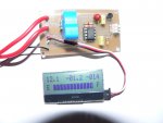
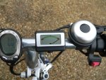
To illustrate the point, the photo below uses a 30 A LEM sensor to record Ah used by an electric boat. No filtering is needed, despite it sensing the current being drawn by a 1.2kW peak BLDC motor. I have another similar unit built in to my electric folding bike, driving an analogue display as a "fuel gauge" (the second photo below) and again no filtering is needed, the sensor (in this case an Allegro one) works fine without it. The bike display can be switched from Ah remaining to instantaneous current, so if the sensor was noisy it would quickly show. Both of these use an 08M, BTW.
 

Attachments

SAborn

Senior Member
My definition of annoying noise may be different to yours.
Annoying noise to me = Doof, Doof, Doof..................................?
And i still cant find a way to filter it out. (well... Bang, Bang, Bang, would fix it, but its not exceptable filtering)
 

John West

Senior Member
Making the assumption that the poster has these technical issues already sorted out to ensure a noise-free system seems a bit of a stretch. All the more reason for such discussions in order to cover all the known variables found in such systems.
 

Blazemaguire

Senior Member
Making the assumption that the poster has these technical issues already sorted out to ensure a noise-free system seems a bit of a stretch. All the more reason for such discussions in order to cover all the known variables found in such systems.
Correct assumption! But keep going, its all food for thought!
 

inglewoodpete

Senior Member
Nope, no spikes with a Hall sensor.

These sensors are now fast enough to do PWM pulse current measurement and control on the fly, too, which means they can be used to do closed loop current control (useful if you want to use torque control rather than speed control on a brushless motor).
Jeremy, Is there any chance that you can post an oscilloscope pic of the output of the Hall sensor when used with PWM on a brush motor? It is something that I, too, have dismissed as being too noisy: perhaps prematurely.:(
 

Jeremy Harris

Senior Member
Jeremy, Is there any chance that you can post an oscilloscope pic of the output of the Hall sensor when used with PWM on a brush motor? It is something that I, too, have dismissed as being too noisy: perhaps prematurely.:(
I'll try and see if I can have a go, although it'll be a bit difficult as the motor needs to be loaded to draw any appreciable current to measure, which means working out a way of strapping something to the bike and then riding up a hill....................

There's plenty of stuff around on the web about current waveforms with properly driven PWM motor speed control though. I've been playing with field oriented control (not with a Picaxe though!) and have used a variation on the scheme that Infineon describe in this application note: http://www.infineon.com/dgdl/AP0805910_Sensorless_FOC.pdf?folderId=db3a3043134aa0ee01134dcf16670067&fileId=db3a3043134dde6001134e2c3cff002f&sId=db3a304435c2940f01363e2fbca26af6 (sorry about the link-click thing). Infineon use a shunt in the return line from the PWM motor control, fed to an ADC, but I'm using separate Allegro sensors in each phase wire from the three half bridge FET drivers. I'm hoping for better motor control by doing this, as the simple way most BLDC motor drives work (PWM'd 6 step trapezoidal commutation) has significant limitations and makes the the motor produce a lot of noise (acoustic, not electrical).

As I mentioned before, provided the PWM frequency is high enough for the LR time constant of the motor, then the current rise time will be slugged right down. The analogy is just like the smoothing capacitor on a rectified supply - too small a value produces voltage ripple. Although the current waveform is pretty nice and smooth (and hence the Hall output is too) the same can't be said of the voltage when using a crude control system. The spikes on the controller supply rails can be quite nasty, and need low ESR capacitors mounted as close as possible to the FETs to keep them under control. I think it's the latter problem that has earned the reputation for PWM being electrically noisy, although with proper design it isn't really. The 4QD web site has a reasonable explanation of the way commutation capacitors are needed to deal with the high dV/dT events at the FETs and the need to match the PWM frequency to the motor LR here: http://www.4qdtec.com/pwm-01.html although it is pretty dated now.
 

fernando_g

Senior Member
kHz).

To illustrate the point, the photo below uses a 30 A LEM sensor to record Ah used by an electric boat. Both of these use an 08M, BTW.
Jeremy I'm not going to hijack this thread, but I will open a new one to discuss the optimal way to do bargraphs in LCD displays, as you nicely have done on the left image on post #14....I've done a few experiments, but they are extremely inefficient, code-wise.
 
Top