Mains voltage PWM motor control

Memran

Member
Hello :cool:

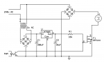
I am trying to design a circuit to control a 240v DC motor, and also keep the high voltage separate from the input PWM (in case of magic smoke).

Since I'm fairly new to circuit design, I am unsure of a few things:

Is it ok to have a common ground between the low and high voltage parts?
Should the ground be connected to the mains earth?
If the current draw on the motor exceeds the capability of the fet, can I add more fets in parallel to multiply the maximum current?
Is it safe to assume the high voltage side can be effectively (and safely) tested at a much lower voltage, say 12v?

Perhaps I've done something stupid in my schematic, so any observations and comments are welcome! :D

Thanks!

Mains PWM.png
 

bluejets

Senior Member
Stay away from 240v mains. Do not know how many times it has to be repeated.

Having said that, there are thyristor controllers out there commercially made for series motors that you can plug in to, assuming your motor has a plug fitted.
 

John West

Senior Member
Welcome to the forum, Memran. What bluejets is trying to say is that circuits working directly with AC mains are dangerous for beginners, or even some of us old tech fellas. While it's not difficult for an experienced engineer to design such a circuit and have it operate safely, there is a lot more involved in such a circuit than one might initially suspect.

As you are planning on operating an electric motor, there is a requirement for protective circuitry for when the motor is shutting off, or is spun by hand, or stalled, etc. Then there is the heatsinking requirement for the driving semiconductor, line filtering and fusing, and a properly grounded shielded cabinet.

Basically, even experienced techs usually opt to purchase pre-manufactured power control modules to interface with mains driven motors. They don't blow up as often. AC mains powered circuits that aren't carefully designed and constructed can blow up in impressive fashion, throwing hot bits out at high velocities.
 

Dippy

Moderator
Heed the advice above.
Your circuit is way off in several ways so don't do it. It will fail. A more considered design is required.

As a slight aside don't assume that because a data sheet says "250V" rating for the MOSFET that you can simply shove it in to that circuit.
I mean this seriously - ask yourself questions; what is the peak V from AC at 240V rms? What kind of reactive Voltage peaks will you get when switching?
How much current can pass with gate drive at 5V?
A MOSFET (rated 250V) isn't a mains switch.
 

MartinM57

Moderator
IMHO, leave everything on your schematic to a commercial and reputable (I.e. not a cheap-as-you-can-find chinese eBay special) HV DC motor controller. Play with your PICAXE off to the left of the schematic ... and I still can't recommend that, as there's still mains voltages all around you.

IMHO, again, your schematic is naieve - PWM'ing a "normal" FET with a 5v gate-source voltage through a 10K resistor with high drain-source voltages and currents is just not going to do what you think - it will either do nothing, get stuck in it's linear zone and overheat and explode, or perhaps "lock on" and be uncontrollable with your motor at full power.

..and then there's running a 240v DC motor directly off full wave rectified AC mains (is that 240 v DC?) with zero protective components anywhere on your schematic or taking into account what happens when the motor overruns when slowing down, or when the power fails and it turns into a generator, are also things that should keep you away from attempting this
 

Memran

Member
Yikes!

Well thanks for your input!
There is clearly a lot more to this than I first thought. You've all successfully talked me out of attempting it.

I am curious though; was there any part of the design which wasn't ludicrous? :confused:

Thanks everyone :)
 

Dippy

Moderator
"was there any part of the design which wasn't ludicrous?"
- yes, the spelling was good :)

I think you should look at some basic motor control and also get a little background on what component specifications mean in the Real World.
Leave mains alone until you have some proper experience.
Many of us here have probably 'experienced' pain resulting from a little knolwedge/learning being a dangerous thing.
 

Goeytex

Senior Member
A good way to do what you need is to purchase a 400v DC Solid State (SSR) Relay rated above the current that your motor will draw. The SSR will probably need a hefty heat sink. The SSR will switch with a logic signal direct from the Picaxe and is optically isolated. Then you will need a DC power supply to convert the mains to DC.

What are you doing with a 240v DC motor? What is the current rating? What is the stall current ?

Don't even attempt to use the circuit you posted, it is dangerous and won't work anyway.
 

BeanieBots

Moderator
In addition to what the others have already said;
Even if you did come up with something both safe and legal, trying to PWM a motor that is being supplied with raw rectified DC won't do what you think. You would need to synchronise your PWM with mains frequency to avoid beat frequencies.
 

AllyCat

Senior Member
I am curious though; was there any part of the design which wasn't ludicrous? :confused:
Hi,

Yes, welcome to the forum also, and the Optocoupler in the lower left-hand corner wasn't a bad idea either. :)

However, the potential "isolation" (safety) produced by a transformer was lost because of the direct path through the Motor/FET. In practice, the transformer and regulator are probably unnecessary, a correctly specified capacitor and a simple shunt regulator (12 volt zener diode) would be cheaper and might actully help to drive the FET better (a few more volts). Or in some applications a Thyristor would be a better choice than a FET.

But as said above, mains electricity is certainly NOT the place to start (and possibly end) learning about electronics.

Cheers, Alan.
 

boriz

Senior Member
How many Watts? You can do this with cheap off the shelf modules if you don't need too much power.
 

fernando_g

Senior Member
If all that you are doing is attempting to master the essentials of motor speed control using a Picaxe, do it a low voltage instead.

Get yourself a mains to 12 volt transformer, and on an auto wrecking yard purchase a fan motor or something.

Several years ago, a nephew was tasked with using a microcontroller to control a three phase bridge for purposes of motor speed control, as a final project.
I suggested him to talk to his teacher and request to do it at low voltage. Permission was granted, and he star-wired three mains to 12 volt transformers, and designed all his circuitry in a very safe manner.
As a plus, he was able to hook up a scope during the project demonstration, to show the waveforms in real time as he changed the speed.
 

tmfkam

Senior Member
Series AC mains motors, if you can wire them appropriately, run very well at relatively low DC voltages. Sir Clive Sinclair came in for ridicule when it was found that the motor in the ill fated C5 was a washing machine motor, but many will work extremely well at 24V although I'd assume that torque will be much lower than when powered at 240V.

Simple PWM circuits for DC motors can be found relatively easily, and need not necessarily include any processing power. I've built many using just a 555.

If you are stuck at using mains voltages, I'd recommend using an IGBT as the 'switching' device. An STGW30 is capable of switching 30A at up to 1,200V they also have an integrated diode for protection against back EMF.

Remember that all low voltage and control sections would need full isolation from the high voltage sections, separate supplies using separate transformers, opto-couplers or pulse transformers for connecting the PWM signals from the control section to the high voltage section and so on. It can be done, but I wouldn't recommend it.

If you make any mistakes either in the building of this, or in the design, the consequences are LETHAL. If you are lucky with your mistakes there will just be an enormous flash and bang followed by the lights going out. If you are unlucky, there will be a flash, a bang and you'll be on your way to the undertakers.

Saying all that... I did build a variable frequency, PWM power control, drive for an induction motor that operates from 48V-250V (AC or DC) supplies and provides a 25Hz-250Hz AC output with the power delivery controlled by the PWM. The 240V AC induction motor used, runs happily at only 48V which could be easily provided by a suitably powerful transformer.
 

JimPerry

Senior Member
Has luck has it I' m still here to tell the story -

40 years ago I was working on Video for the Rolling Stones in Hyde Park. The onstage Roadies kept unpluging our power .. I had a "great" idea - wire a cable with two 13A plugs ... my workmate threw me the exposed (live) plug while I was holding the (earthed) scaffold --- I don't remember much of the concert :mad:

MAINS VOLTAGE CAN KILL :rolleyes:
 

MartinM57

Moderator
I think this thread has run it's course - we don't really need lots of examples of how this could be done, or the dangers of doing it. It will only encourage others :(

OP has made the right decision (IMHO) and moved on....

PS welcome to the forum tfmkam :)
 
Top