mA output on transducers
- Thread starter gtslabs
- Start date
I had to look this one up.
I Googled up a couple of data sheets for pressure transducers that operated with a 4-20 mA current loop two wire intereface.
In each, I found a chart of transducer power voltage vs loop resistance. With that in hand, I brewed up the sketch below.
When you set up your Picaxe interface, choose your transducer power voltage (probably to match the voltage of a power supply you have on hand) then choose the loop resistance for a value that is within the transducer's operating range and is a value that will produce a suitable ADC voltage range for the 4-20 mA drawn by the transducer and some overhead for fault conditions.
(One of the data sheets said that a fault condition was designated by a current draw in excess of 21.75 mA. It didn't state how much in excess. Because of this, and because of the possibility of a short on the wiring to the transducer, I recommend that you include the 1 k series resistor and the 5.1 volt zener diode, as shown.)
Hope this helps,
Tom
Attachments
-
 2.6 KB Views: 174
hippy
Ex-Staff (retired)
Not quite sure I understand but, if they offer a resitance proportional to pressure it should be possible to put them on one side of a potential divider and measure the resultant voltage, just like reading an LDR or thermister. Depending on their source resistance and actual value change it may be necessary to pre-condition teh signal with op-amp amplifiers and so on.
leftyretro
New Member
This is a standard instrumentation interface used in the process control industry. The big advantage of the 2 wire loop powered 4-20 ma 'instrument loop' is that the transmitter can be hundreds even a few thousand feet away from the receiving electronics and of course the loop powers the device as well as measures the process value.
These 'transmitters' are very low power devices as the can only utilize the 0-4ma overhead power for device power as the measurement value determines where the 4-20 ma level will be at any specific time. The 4ma 'zero' value also allows the receiving electronics to be able to tell the difference between a zero measurement value and a open loop (broken wire) 0 ma value. This 4ma starting measurement value is called a 'live zero'
Anyway these are normally powered with a 24vdc power source however some will operate down to near 12vdc. You wire a series loop between the positive voltage source, the field transmitter and a 250 ohm resistor and back to the common from the power source. You measure the voltage drop across the resistor and that will vary between 1-5vdc corresponding to the measurement value in the 4-20ma loop. Of course in your software program you have to factor the scaling value that this 1-5 vdc represents. This 1-5vdc should be able to be measured easily by a picaxe A/D input. So your only challenge is the higher then normal DC voltage power source needed by the device. Again 24vdc is the standard value to power these devices and their loop.
Lefty
Last edited:
Thanks, Lefty. Excellent explanation.
I infer two things from your explanation and from the data sheets I skimmed earlier.
First, for very long cable runs, the resistance of the cable should be taken into account when choosing the loop resistance value from the resistance vs voltage chart in the data sheet.
Second, depending upon the supply voltage, it might be possible to exceed 5 volts dropped across the discrete loop resistor. In that case, it would probably be a good idea to split the loop resistor into two series resistors, with the ADC voltage measured across the bottom resistor.
Tom
Last edited:
leftyretro
New Member
First, for very long cable runs, the resistance of the cable should be taken into account when choosing the loop resistance value from the resistance vs voltage chart in the data sheet.Thanks, Lefty. Excellent explanation.
I infer two things from your explanation.
First, for very long cable runs, the resistance of the cable should be taken into account when choosing the loop resistance value from the resistance vs voltage chart in the data sheet.
Second, depending upon the supply voltage, it might be possible to exceed 5 volts dropped across the discrete loop resistor. In that case, it would probably be a good idea to split the loop resistor into two series resistors, with the ADC voltage measured across the bottom resistor.
Tom
Those tables allow one to factor in the resistance of long wire runs to see if there is enough 'compliance voltage' left over for the field transmitting device to actually power the device, however the process instrumentation control engineers usually never try and calculate total loop resistance as in practice a 24vdc voltage will work for several thousands of feet of loop wire. The transmitter actually measures the total loop resistance and adjusts it's output resistance such that it sets the total loop current to the specific 4-20ma value that it needs to. The 250 ohm 'measurement' resistor is the standard voltage drop resistor almost always used in the vast majority of process control receiving electronics, however one is free to use any lower value and scale the measurement in software, however one usually wants to utilize as much of the total A/D resolution range as possible.
Second, depending upon the supply voltage, it might be possible to exceed 5 volts dropped across the discrete loop resistor. In that case, it would probably be a good idea to split the loop resistor into two series resistors, with the ADC voltage measured across the bottom resistor.
Well worst case would be a field transmitter direct short where then 96ma (24/250) would flow and the full 24vdc would be seen on the positive side of the 250 ohm resistor, so some kind of protection for the picaxe A/D input pin might be justified, no matter what value 'dropping resistor' is used. I would think a 5.1v zener diode would work well placed between common and the picaxe a/d input pin.
Lefty
BeanieBots
Moderator
What retrolefty said.
The whole idea of the 4-20mA drive standard is to eliminate line impedance over long cable runs. Also, very noise immune for analog levels.
There are special receiver chips available to convert 4-20mA into 0 to 5v but I don't know any number off the top of my head.
I would go with the 250R method unless you particularly need to utilise the benefits of a current loop. However, I would NOT recommend the 5.1v zenner(they start to conduct at much lower than 5v). Simply stick another resistor (22k) between the 250R and the ADC input as a current limit should the voltage go above 5v.
leftyretro
New Member
"Simply stick another resistor (22k) between the 250R and the ADC input as a current limit should the voltage go above 5v."What retrolefty said.
The whole idea of the 4-20mA drive standard is to eliminate line impedance over long cable runs. Also, very noise immune for analog levels.
There are special receiver chips available to convert 4-20mA into 0 to 5v but I don't know any number off the top of my head.
I would go with the 250R method unless you particularly need to utilise the benefits of a current loop. However, I would NOT recommend the 5.1v zenner(they start to conduct at much lower than 5v). Simply stick another resistor (22k) between the 250R and the ADC input as a current limit should the voltage go above 5v.
That does sound like the easiest protection method, the built in pic clamping diodes are a nice feature. I assume worst case 24vdc and 22k series resistance is sufficient? I've never seen or looked for a calculation method for utilizing the clamping diodes.
Lefty
BeanieBots
Moderator
Can't say that I've ever seen anything formally documented but my personal rule of thumb is limit to 2mA. (22k @ 24v being just under 1mA).
Add an external schottky and you could go up to a few amps assuming the PICAXE supply can take it.
Add an external schottky and you could go up to a few amps assuming the PICAXE supply can take it.
If you are building a pressure transducer have a look at http://drvernacula.topcities.com/RFDataLink.htm
I never managed to get current loops to work. Admittedly I was using wires in the open air over 500 metres with high tension power lines overhead. DC current would go in one end and AC current would come out the other! I probably could milk off some power if I felt so inclined. I used a picaxe to send binary data with a baud rate of 0.1 with lots of current to drive an old fashioned relay clicking once a second or so. This is the beauty of a picaxe - you can take an analog voltage and turn it into slow binary code (or morse code or whatever) with one chip, send the data long distances, re-encode it with another chip up and transmit it at 2400baud straight into a computer.
Of course, if you are not sending the data any distance and you happen to have some 4-20ma current loop transducers, just use the circuits described above. If you haven't got a transducer I would go for the wheatstone bridge ones as they are the cheapest ($23Au).
Thanks for all the help. Right now I am using loadcells with a 3 mv/V output and an AD7730 24 bit ADC. I get a lot of noise just at my breadboard. This is why I am considering the mA output for my pressure transducers. Do I need a very stable voltatage supply or will a typical wall wart work. I need more resolution than the 12 bit from the Picaxe so I would still need to measure my voltage across the resistor with the AD730.
leftyretro
New Member
The Picaxe is a 10 bit D/A not 12 bits. Current loop voltage source doesn't normally require super regulation as the transmitter will try and maintain a constant current, however if you are using a 12 bit A/D or more you will need every trick in the book to keep noise down to LSB value. Even high quality pressure transmitters probably are .5% accurate so 12 bit A/D may be overkill.Thanks for all the help. Right now I am using loadcells with a 3 mv/V output and an AD7730 24 bit ADC. I get a lot of noise just at my breadboard. This is why I am considering the mA output for my pressure transducers. Do I need a very stable voltatage supply or will a typical wall wart work. I need more resolution than the 12 bit from the Picaxe so I would still need to measure my voltage across the resistor with the AD730.
Lefty
Last edited:
Lefty, I have a 2000 psi pump with a 8" diameter piston ram that I am measuring the force calcualted from the pressure. So I was going to get a 2000 psi transducer. At full pressure I would be generating 100,480 lbs force on my ram. I need a minimum resolution of 10 lbs resolution. If I understand the resolution correctly then a 10 bit (1024) would give me a 100,480/1024 = 98 lbs per count. A 16 bit would give me 1.5 lbs force resolution. Am I missing something?
My existing machine has a 10,000 psi pump, 10,000 pressure transducer and a Red Lion PAXS display which is 16 bits. I am trying to emulate that readout on my computer. It is only good to 10 lbs force but can only be calibrated down to 10% of the 250,000 lb capacity of that machine.
My existing machine has a 10,000 psi pump, 10,000 pressure transducer and a Red Lion PAXS display which is 16 bits. I am trying to emulate that readout on my computer. It is only good to 10 lbs force but can only be calibrated down to 10% of the 250,000 lb capacity of that machine.
BeanieBots
Moderator
You won't have much luck with breadboard and 24 bit analogue work.
The noise and contact voltages will be comparable to the signal you are trying to measure.
When working with very small signals and high gains, I don't even use solder because of the thermocouple effects that can be generated. Gold wirewrap is the industry standard for such connections. Wrap direct to the pin before fitting in the socket.
Keep anaolgue and digital lines well seperated.
The datasheet for the 7730 is here:-
http://www.analog.com/UploadedFiles/Data_Sheets/AD7730_7730L.pdf
It quotes power supply rejection at 90dB which is quite good but that will still require a very clean power supply. A good clean supply will also prevent supply ripple from getting into other areas which might not be so tollerant.
The output of the 7730 is digital so won't need to worry about the PICAXE ADC which, by the way is 10-bit not 12-bit.
Keep the 7730 as close as possible to the sensor and send the digital over distance, not the other way round.
leftyretro
New Member
"Am I missing something?"Lefty, I have a 2000 psi pump with a 8" diameter piston ram that I am measuring the force calcualted from the pressure. So I was going to get a 2000 psi transducer. At full pressure I would be generating 100,480 lbs force on my ram. I need a minimum resolution of 10 lbs resolution. If I understand the resolution correctly then a 10 bit (1024) would give me a 100,480/1024 = 98 lbs per count. A 16 bit would give me 1.5 lbs force resolution. Am I missing something?
My existing machine has a 10,000 psi pump, 10,000 pressure transducer and a Red Lion PAXS display which is 16 bits. I am trying to emulate that readout on my computer. It is only good to 10 lbs force but can only be calibrated down to 10% of the 250,000 lb capacity of that machine.
Hum, well your transducer measures pressure not force. The force is of course a calculated value of pressure X area of piston. A strain gauge would be the sensor used if you wanted direct measurement of force.
Accuracy can a complex topic. There will be in any measurement system something that defines the limit to total accuracy and therefore usefull resolution, most likely the sensor. If a 0-2000 psig sensor/transducer has a .1% accuracy (which would be a very good value and not cheap) then .1% X 100,480 lbs of force = +/- 100 lbs of force accuracy at full scale, no?
The fact that your present display has 16 bits of resolution or that you do a 12 bit A/D conversion does not improve the basic resolution accuracy defined by the sensor. Displaying more resolution then the sensor/transducer can deliver only gives a false sense of increased resolution accuracy.
So check out the accuracy and resolution specifications of your selected sensor/transducer carefully to see what you can actually obtain in the way of useful resolution accuracy. A desired +/- 10# of resolution of a 100,000# top of range would require a sensor with .01% or better accuracy, probably not obtainable or affordable outside a research lab environment.
Lefty
Mycroft2152
Senior Member
One of the best explanations of accuracy and resolution that I've seen.
Once again a reminder that the PICAXE uses the power supply as the reference voltage for the ADC. a tightly regulated power supply is a must.
Once again a reminder that the PICAXE uses the power supply as the reference voltage for the ADC. a tightly regulated power supply is a must.
"I recommend that you include the 1 k series resistor"
I finally got my sensor in and I used a 216 ohm resistor to start with and at 4 ma I am reading a voltage of 0.85 v. But When I add in the protection resistor that voltage changes to 0.60 v. I have it in series with the ADC pin.
I found this from axe001_pcb.pdf
"All 5 inputs use a 10k pull down resistor, it may be necessary to replace this resistor with an alternate value if using input 0-2 as low-resolution analogue inputs."
What resistor value would not change the voltage reading?
BeanieBots
Moderator
gtslabs, the "series" resistor should not effect the voltage at all.
You have created a voltage divider as intimated by Dr_Acula.
There should be nothing on the ADC pin except the "series" resistor.
Remove the pull-down resistor completely. It's job is being done by 216 ohm resistor. The circuit should be the same design as the download circuit. NOT a potential divider.
I have a photo of my breadboard:
http://gts-labs.com/RC018.jpg
I think the problem is with the voltage source. I am using a 12V source to power the sensor and to also power the picaxe thru the 5V regulator. I noticed that I only get the 0.6V reading when I have the Ain wire connected from the Picaxe to the 10K resistor. Otherwise it is reading the correct voltage when not connected.
How should I isolate these sources if that is indeed the problem.
BeanieBots
Moderator
A diagram would have been better.
It looks to me like serin from the 3.5mm socket goes to ADC1 input!
It looks to me like serin from the 3.5mm socket goes to ADC1 input!
GTSLabs, I assume the plug in your pic is feeding your Xdcer. If it is, pull the green ground wire off completely and check your voltage again. Connected to the Picaxe, you shield yield .85V again.
Then replace the 216 ohm resistor with a 250 ohm resistor. That'll give you 1V at 4mA and 5 V at 20mA.
From what I see in your pic, the green wire is grounded to the 0v rail on your 5V side. You then have another ground going to the 0V rail on the 12V side through the 216 ohm resistor. By having the green wire in place, the electricity will take the path of least resistance(the green wire) instead of going through the 216 ohm current-sense resistor. My guess is that the .6v you read when connected to the adc pin doesnt really change very much with pressure change.
Change that 216 to a 250 and pull the green wire. That should give you the results you want.
Dr Acula is correct, the schematic is right. But, the green wire isnt represented on the schematic. If it were, it would be connected between the 10k and 216 and go straight to ground effectively bypassing your 216. Your meter will read correctly across it but when connected to the picaxe, the circuit completes through picaxe ground which has 216 ohm less resistance because of the green wire.
Last edited:
I presume the 216 ohm resistor is actually the 220 ohm resistor in the circuit that happens to measure 216 ohms? Also I presume the red and green leds are special leds with internal current limiting resistors?
Is the 1012 consistent? It may be fluctuating rapidly and only a cro will see that though you can use debug in a loop and see if the values are changing. Sometimes it helps to put a cap (eg 0.1) across the ADC input and ground. I've always found connecting an ADC to the power supply gives 1023.
No ground loops but the current from the green led will be pulling the ground up a bit at that led and that is also going to pull the value high at the bottom of the transducer. Maybe pick a common ground point (I usually use the 5V reg) and bring anything that draws more than a few ma directly to that point. If it is on a PCB use a "star" configuration on the ground rather than a ground wire that loops all over the place. Maybe just take the leds out for the moment - I think they are drawing current and pulling voltages up. Put your multimeter ground lead on the middle leg of the regulator and go around the ground circuits with the +ve multimeter lead and see if the ground really is ground everywhere. You might find it is a few mv above ground in a few places.
BeanieBots
Moderator
^^ what the Doc says ^^
BeanieBots
Moderator
How are you making the connection to the power rail to get the 1012 reading?
Are you connecting direct between power pin and ADC pin or pulling the 'far' end of the resistor to some obscure point on the power rail?
Are you connecting direct between power pin and ADC pin or pulling the 'far' end of the resistor to some obscure point on the power rail?
Another circuit?
Hi guys,
I'm about to make the switch from 0-5 V transducers to 4-20ma transducers for all the reasons mentioned by retrolefty. One really good one is two wires and long cable runs, very robust in bad environment. I have 24 V or 12 V from the machine (big mining machine) anyway, so that is the way to go.
I purchased an amplifier module from these guys:
http://www.oceancontrols.com.au/data_acquisition/dual_amp.htm and there is a circuit diagram attached. Basically you can use the module as an amplifier or reducer for your transducer.
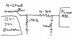
Also provided is an option to connect a 4-20ma transmitter, which would only have two wires. One "excitation voltage" wire goes to the 24V or 12V and one to the input of the amplifier module. On the input of the module there is an optional 100 ohm resistor between the input and ground. This gives a voltage across the resistor of 0.4 to 2V, but i figure this can be 250 ohm, to give a voltage of 1.0 to 5.0 v,.
The op amp is high impedance, just like the picaxe a/d. but there is no zener, just a 50K resistor, between the 100 ohm and the non inverting input. I figure anything above 10K (learned that from a previous thread) will protect the input of the op amp or in this case picaxe from too much current from the high voltage in case of a dead short.
Am i on the right track here? I'm about to spend hundreds of dollars on 4-20mA transmitters.
Michael
Hi guys,
I'm about to make the switch from 0-5 V transducers to 4-20ma transducers for all the reasons mentioned by retrolefty. One really good one is two wires and long cable runs, very robust in bad environment. I have 24 V or 12 V from the machine (big mining machine) anyway, so that is the way to go.
I purchased an amplifier module from these guys:
http://www.oceancontrols.com.au/data_acquisition/dual_amp.htm and there is a circuit diagram attached. Basically you can use the module as an amplifier or reducer for your transducer.
Also provided is an option to connect a 4-20ma transmitter, which would only have two wires. One "excitation voltage" wire goes to the 24V or 12V and one to the input of the amplifier module. On the input of the module there is an optional 100 ohm resistor between the input and ground. This gives a voltage across the resistor of 0.4 to 2V, but i figure this can be 250 ohm, to give a voltage of 1.0 to 5.0 v,.
The op amp is high impedance, just like the picaxe a/d. but there is no zener, just a 50K resistor, between the 100 ohm and the non inverting input. I figure anything above 10K (learned that from a previous thread) will protect the input of the op amp or in this case picaxe from too much current from the high voltage in case of a dead short.
Am i on the right track here? I'm about to spend hundreds of dollars on 4-20mA transmitters.
Michael
How long is the cable run? And have you prototyped a transducer and checked it does outputs the correct values and they are not too near the upper or lower range?
I am just thinking of an early experiment I did with current loops on 500 metres of open fence wire with a high tension line overhead. The AC volts swamped the DC current. In general terms, the longer the run, the more robust the data transmission method. Anything more than a few metres and I'd look at using a picaxe to convert the current loop to RS232 (and implement it with + and -12V using the proper interface chips). Anything more than 50 metres - drop the baud rate down to 300. Are you going longer distances than that?
I am just thinking of an early experiment I did with current loops on 500 metres of open fence wire with a high tension line overhead. The AC volts swamped the DC current. In general terms, the longer the run, the more robust the data transmission method. Anything more than a few metres and I'd look at using a picaxe to convert the current loop to RS232 (and implement it with + and -12V using the proper interface chips). Anything more than 50 metres - drop the baud rate down to 300. Are you going longer distances than that?
Cable runs and Transsmitters
Hi Dr_Ac
The cable runs are not that long i guess, at 12m, but it is a 650 Tonne machine, that's 650 tonne of steel, which i figured might have an electrical influence. the mA transducers are meant to be preferred in a bad electrical environment, i thought, as is the twisted pair cable Peter M mentions. I'm getting spiking in the 0-5V transducers i am using now. Also, for some of the non specialist trades people i have to work with two wires = less mistakes that three wires.
To purchase, Transducers 0-5V and 0-10V are the same price as 4-20 mA transmtters. As Retrolefty mentioned earlier in the thread the transmitters are more industrially common, as these are typically used with PLCs - expensive alternative to the Picaxe.
Also, someone mentioned "live zero". If i use the resistor combo, as per attached sketch, plagiarised from the ocean controls module,and use say a precise 240 ohm resistor between input and ground, then the output range for the 0-4 Bar would be from 0.96 V to 4.8 V. I could use code to highlight a "Transmitter error" on the LCD screen if the voltage was below 0.96 - Open circuit, or above 4.8 = short circuit. This would prompt a repair, rather than aimlessly collect useless data. The 10 - 50K resistor would limit the current input to the picaxe ADC to milliamps if there was a short, so it would not be damaged (well the Op amp in the Ocean Control circuit isn't)
I have not prototyped, but these things are pre calibrated and fixed, 4 mA = zero Bar, and 20 mA is the maximum range of the transducer. In my case 4 Bar or 60 psi would be about perfect. I will do a calibration check with actual pressure.
There should not be a need to convert to digital and RS232. If i was going 500 metres I would be using x Bee modules, much cheaper than paying guys to run cables and having it damaged.
So
1) Does my circuit look OK, and
2) do we really need the zener if the current to the ADC is limited to milliamps?
Michael V
Attachments
-
 90.6 KB Views: 32
leftyretro
New Member
Zener should not be required as your series resistor would limit current into the ADC pin.
Good luck
Lefty
Good luck
Lefty