LTC6903 SPI acknowledge transfer

MPep

Senior Member
Hi all,

I am going to use the above chip. Datasheet here.
I am a little puzzled over the datasheet's mention of
When the SEN line is brought LOW, serial data presented
on the SDI input is clocked in on the rising edges of SCK
until SEN is brought HIGH. On every eighth rising edge
of SCK, the preceding 8-bits of data are clocked into the
internal register. It is therefore possible to clock in only
the 8 {D15 - D8} most significant bits of data rather than
completing an entire transfer.
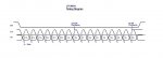
Does this mean that the following code should work okay?
Code:
    low CS
    hspiout (freqhigh)
    pause 1
    hspiout (freqlow)
    high CS
Where FREQHIGH and FREQLOW are byte-wide variables.

I suspect that the following should not work
Code:
    low CS
    hspiout (freq)
     high CS
Where FREQ is a Word-wide variable.

MPep.
 

westaust55

Moderator
hspiout will only accept byte values/variables not word variables.
However you can send multiple bytes in the same hspiout commands so

hsipout (highfreq, lowfreq)

will work.
 

MPep

Senior Member
Would that then give the necessary (single) clock cycle as an acknowledge cycle? Between the HIGH and LOW bytes?
 

westaust55

Moderator
The timing diagram on page 8 of the datasheet does not indicate any acknowledge is sent for SPI comms.

An ACK response bit is usually associated with i2c not SPI comms

See i2c timing diagrams on page 9 of the datasheet
 

hippy

Technical Support
Staff member
Are you sure you're looking at the LTC6903 SPI sequence and not the LTC6904 I2C timing diagram ?

The SPI timing diagram appears to be drawn wrongly; there's not 16 clock pulses or 16 clocking edges no matter how one counts them. From the textual desciption it seems to be simple enough, lower SEN, for each bit of data set SDI, raise then lower SCL. Either put out out 8 or 16 data bits and 8 or 16 raising and lowerings of SCL, then raise SEN.

I would suggest getting it to work by bit-banging before moving on to HSPIOUT.
 

Dippy

Moderator
I don't understand what hippy says... maybe my coffee is too strong? :confused:
http://cds.linear.com/docs/Datasheet/69034fc.pdf

Am I looking at the right Data Sheet?
At the bottom of page 8 I see 16 bits for SPI (LTC6903) clear as a bell.


Followed by the write method described top of Page 9.
When the SEN line is brought LOW, serial data presented
on the SDI input is clocked in on the rising edges of SCK
until SEN is brought HIGH.
means...
// For manual bit bang
Clock Low. // Clock pin low​
Set Data // Select bit and set data pin high or low
Clock High .. repeat for 8 or 16 bits.

For HSPI you'd set idle low and clocking on leading edge.


It is therefore possible to clock in only
the 8 {D15 - D8} most significant bits of data rather than
completing an entire transfer.
means simply ...
As D15-D8 are the MSbits then this means you are can write in a single byte if you need/want to.

Note that if you delay between D8 and D7 you may screw up.
So, one byte or two bytes... upto you.
 

Dippy

Moderator
Oh, I see what you mean. I was just looking at the SDI.

Ah well, just ignore the drawing error and put it down to half-sloshed Proof-readers at Linear (who obviously can't count like me) :)

Maybe if you point out the error to Linear Techincal you'll ge a freebie.;)

The rest of what I said above is valid hopefully.
Looks easy as pie.
You should be able to code something up now MPep, or maybe a keen type will write it for you... Westy won't be able to contain himself ;)
 

MPep

Senior Member
Are you sure you're looking at the LTC6903 SPI sequence and not the LTC6904 I2C timing diagram ?
Oops :(................ with egg on face.

You're right of course. Just that the diagrams and the descriptions are not matched up on the same page!
Sorry about that folks. Should indeed be easy enough to do.

@Dippy,
And no, I was not out for someone else to write my code for me!

As stated, I don't have hardware just yet. Wanted to see if I could code a program using Datasheets first.

Now unlike some people, I wont go deleting the original post!!!:eek:

Thanks all,
MPep

------------------------------------------------------------------------------------------------------------------
*Update: I have informed Linear Technologies of the incorrect timing diagram. Will report back here with their response.


**Corrected timing diagram now attached.
 

Attachments

Last edited:
Top