low voltage (1.8vlts) output from pin - when set high?

Hi peeps, I am only getting 1.8volts from pin B.3 when 'high' it's not connected to anything and chip is powered by 3 x AA batteries.
Any clues would be appreciated?
The other three output pins are only powering LED's via appropriate resistors.
Thanks in anticipation
 

kranenborg

Senior Member
... and in addition to that, could you you post both the program and a picture of the circuit diagram here? There are multiple causes possible, both internally and externally from the P
icaxe ... .
/Jurjen
 

Goeytex

Senior Member
1) Are the batteries at acceptable levels ? Measure the voltage between the Picaxe +V and 0V pins. What is it ? Does it change when the program runs?

2) Disconnect everything from the Picaxe except the batteries. Let the program run and check the 'high' voltage on B.3 again. Did it change?

These steps may give you/us some direction in regards to troubleshooting

As others have asked, tell us what Picaxe chip it is and also what dev board it may be on ( if any) . A circuit diagram may be useful as well as a photo of your setup if possible.

Goey
 
Thanks all!
The circuit is constructed on strip board and the battery voltage is 4.6
Please excuse the unprofessional, and probably unconventional, circuit diagram....

Arrrgh!!! can't seem to attach anything to this post GRRRR :-(
Bloody hopeless case, I am.....
 
I shall try again to attach circuit diagram and code - if this fails, please choose a nice care home for me...
1673708054883.png

start:
let w1=0
wait 5
high B.4 ;timed activation delay led
readadc C.4,w1
let w2=w1*100

Go:
if pinC.3=0 then goto Go
high b.1 ;Green Led On
high b.3 ;Relay On
high b.2 ;Red Led already activated signal
pause w2
low b.1 ;Green Led Off
low b.3 ;Relay Off
goto Go
 

papaof2

Senior Member
I don't see a reverse voltage protection diode across the relay. The inductive "kick" when the relay is turned off can exceed the maximum allowable PICAXE pin voltage. I suspect that PICAXE pin B.3 has been damaged.

Check the PICAXE manual on Microcontroller Interfacing Circuits (Manual 3?) for the proper way to drive a relay. Don't replace the chip or move the relay to another pin until after you have added that diode - a 1N4001 is probably adequate. If I'm not correct, someone will pop up with the proper values ;-)
 

The bear

Senior Member
Thank you for the necessary information.
I don't see any capacitors.
Safer to use a transistor or FET to drive a relay, acts as a buffer to the picaxe (Just my opinion).
Are you sure the relay is 500R? Could be 50R.
Good luck, stick with it.
 

Tvmender

Active member
Be careful not to overload the individual pins. I think they are limited to 10mA each (need to check).

I would recommend (like The bear and papaof2) that the relay is driven using a transistor or FET. Relays can take a big thump of current. The 1N4001 would suffice as a flyback diode. As The bear said, check that its not 50R or you could be pulling around 90mA!

Individual resistors on the LEDs would also be better as they will be even brightness.
 

inglewoodpete

Senior Member
Be careful not to overload the individual pins. I think they are limited to 10mA each (need to check).
According to the PIC12F1840 (08M2) and PIC16F1825 (14M2) data sheets, 25mA is the absolute maximum current for a pin (source or sink). It is wise to stay well away from this figure.
 
Last edited:
Thanks to all for your advice and patience!
I routinely fit a spike suppression diode across any inductive loads but omitted to show it on the diagram - my mistake...
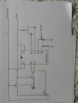
I tried the suggestion of disconnecting all outputs and running the program whilst checking voltage on the pins:
B1,B2 & B4 were fine but B3 was providing only 1.4 vlts and B5 2.4 vlts.
I had tried using a TIP 122 to drive the relay but this was no more successful .....
don't know if it's important but the cross hatched globe in the diagram is a PIR sensor.
I might try driving the relay from one of the 'good' pins - once I've check the current draw of the relay (which is 500 ohms)
Prior to that I'm going to program a new chip and run it without any outputs connected and check if it's my wiring or a duff chip.
I'll let you know - unless it's my incompetence :oops: in which case i'll destroy the evidence and deny all knowledge
thanks again :)
 

Technoman

Senior Member
I am a bit puzzled by your program.
W2=0 (=W1) means almost no pause...
If C.3=1 then you activate/desactivate b.1 and b.3 at "high" frequency within a short loop. On a scope you should see a "square" signal but on a voltmeter you'll get an average value (?).
According to #11, I don't understand why b.1 is ok but not b.3.
 
Ah, yes - i get it now - D'oh!
I had realised today that when the pot centre contact was at the nought volts level the voltages were all 'up the spout' and your point explains that, thanks!
When I set the pot to mid level all voltages seemed to be correct Yay!
I shall provide each LED with it's own resistor and adjust the program and see how it goes.
 

hippy

Ex-Staff (retired)
I would guess the 600R relay coils are reducing resistance as current flows and that's pulling the voltage down on those pins.

Write some simpler code which just slowly toggles the the two pins in turn, check the pin voltage, then remove the relays and test again. Something like -
Code:
Do
   High B.1 : Pause 2000 : Low B.1
   High B.2 : Pause 2000 : Low B.2
   High B.3 : Pause 2000 : Low B.3
   High B.4 : Pause 2000 : Low B.4
   Pause 2000
Loop
 
Thanks chaps/Ladies
'Technoman' was correct - It was all the fault of my thoughtless coding... I have a hand held oscilloscope and used it to check the output from the pins: a high frequency square wave! which explains the apparent low voltage my multi meter was showing and the weird resistance results I was getting from the relay contacts - something in the order of 1.3K?
So I've tweaked the code and if it works (once I've returned from the shopping trip my wife says is 'vital' :cautious:) i'll re-program the chip and see how it goes.
Thanks to everyone who has offered advice and guidance (y)
 

Technoman

Senior Member
Ooops, I have overlooked the readadc instruction in your program for adjusting the delay between 0 and 255*100=25500 or 25,5s.
Being outside of the main loop, you'll need a reset to change the delay ; it's your choice.
 
Thanks 'Technoman'
It was my intention to have to switch it off before changing the activation time - but thanks, it's appreciated (y)
All seems to be working OK now! Yay!:giggle:
(I think the whole thing started to go wrong when my brain stopped working - at least it wasn't my circuit wiring.....)
 
Top