Looking for +3v to -3v variable frequency signal to drive a single clock stepper

Hi guys,

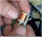
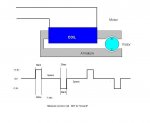
I'm trying to generate an alternating current signal to drive a quartz clock stepper motor. There is only one coil. I believe the drive relies on alternating the poles by cycling the drive voltage. These are not expensive dual coil movements.

Space is at a premium. I would like to know how to do it with a PIC (since I might be looking at sensing a position of the shaft, at some point down the road) but have been told it can be done with a single 555 timer with a capacitor or a pair of 555's.

I've been having trouble searching Google for this since all "DC-AC inverter" searches lead me to power inverters for generating mains voltage from a 12v DC power source. What should I be searching for (in terms of schematics/circuit designs on the hobby electronics sites)

Thanks
Nitrous
 

geoff07

Senior Member
It depends on what you want. Frequency? Variable? How to be varied? Accuracy? You can use two output pins in anti-phase to generate your signal. An smd Picaxe 08m2 will be smaller than a 555 plus capacitor etc.

Define your terms and if I guess right the app is almost trivial with a Picaxe.
 

nick12ab

Senior Member
Does the voltage need to go negative relative to 0V?

If it's just a coil that isn't connected to anything else then it doesn't matter what the voltages are. Simply use a H-bridge.
 
It depends on what you want. Frequency? Variable? How to be varied? Accuracy? You can use two output pins in anti-phase to generate your signal. An smd Picaxe 08m2 will be smaller than a 555 plus capacitor etc.

Define your terms and if I guess right the app is almost trivial with a Picaxe.
Trivial would be nice :)
The frequency would be of the order of 20-40hz. I would like to have an on/off switch and a switch (magnetic reed) to switch between two frequencies. Ie 20/40hz or 1/40hz but even better would be a ratiometric Hall Effect Sensor that varies the frequency between 1 and 40hz based on proximity to a neodymium magnet :)

Accuracy is not very important. +/- 10% would be fine. I'd like to power it with a 3.7v LiPo battery. At some point, I'd like to be able to do more with it, but this is my start. I think you've nailed it with two signals 90 degrees out of phase. I think square wave would be fine.

Is there a common use for such a PICAXE circuit/code snip it (that would let me search for it)

Thanks
Nitrous
 
Last edited:

geoff07

Senior Member
Code:
synbol C_slow_half_period = x 'approx 25 (mS) for 20Hz half cycle
symbol C_fast_half_period = y
do
   if input=1 then 
      halfperiod = C_slow_half_period
   else
      halfperiod = C_fast_half_period
   endif
   high out1
   low out2
   pause halfperiod
   low out1
   high out2
   pause halfperiod
loop
end
This is pseudocode (i.e. you still have to write the program around this skeleton). It has imperfections - the input test will alter the length of one of the half cycles. There are ways to fix that (use an interrupt, another test in the other half cycle, etc). You need to work out the I/O pins and the circuit.

Frequency should be no problem even with the slowest smallest Picaxe. The reed switch would pull the input high against a 10k pulldown resistor. Debounce not necessary. Accuracy better than 10% once you work out the right pause length. 3.7v no problem if you pick the right chip (probably they all work at that voltage these days). If it is battery powered, checkout ways of reducing power consumption. They are 180 deg out of phase, by the way!

edit: forgot the hall effect: well, get phase 1 working and by then you will know how to add features. The manual is your friend.
 
Code:
synbol C_slow_half_period = x 'approx 25 (mS) for 20Hz half cycle
symbol C_fast_half_period = y
do
   if input=1 then 
      halfperiod = C_slow_half_period
   else
      halfperiod = C_fast_half_period
   endif
   high out1
   low out2
   pause halfperiod
   low out1
   high out2
   pause halfperiod
loop
end
This is pseudocode (i.e. you still have to write the program around this skeleton). It has imperfections - the input test will alter the length of one of the half cycles. There are ways to fix that (use an interrupt, another test in the other half cycle, etc). You need to work out the I/O pins and the circuit.

Frequency should be no problem even with the slowest smallest Picaxe. The reed switch would pull the input high against a 10k pulldown resistor. Debounce not necessary. Accuracy better than 10% once you work out the right pause length. 3.7v no problem if you pick the right chip (probably they all work at that voltage these days). If it is battery powered, checkout ways of reducing power consumption. They are 180 deg out of phase, by the way!
Thanks.
Will 180 degree out of phase not cancel each out? Does PIC command structure have the ability to create a -ve signal, without ancillary hardware? Likely need an output transistor or MOSFET to source greater current, right?

I'm going to be doing some PIC reading this week.
Thanks again,
Nitrous
 
I took a look at this link. Certainly this answers some questions but it seem to be going from 0-5v (or 10v) but I need a signal that goes from -X to +X volts. Probably pretty trivial for someone who knows, but... :)
Nitrous

EDIT: this is somewhat cryptic.
If you connect a piezo between two signal lines, one inverted, when one signal is high the other is low so you get the same +current, when the first signal goes goes low the other goes high ( as opposed to staying at 0V ) so current then flows the other way, -current.

this reminds me of a 220v house circuit made up 110volt between the neutral and one of the hots. But I don't see this as -ve 110v.

Still puzzled in Canada. :)
 
Last edited:

geoff07

Senior Member
Negative is a relative term. This gives you two voltages, 3.7v apart, that swap places each cycle. As you are battery powered, there is no ground in the chip circuit. Just connect the coil across the two outputs (assuming current draw is ok but for a quartz clock I'm assuming very low power. The clocks I have dissassembled use a chip powered by an AA batt (1.5v) and a watch crystal to send pulses of opposite polarity to an escapement solenoid, and I'm assuming yours is similar from your description. If you need higher power then you can use amplifiers of various kinds, but polarity is still relative.

Read about Picaxe, not PIC (the underlying chip, but hidden from view to make life easier).
 
Does the voltage need to go negative relative to 0V?

If it's just a coil that isn't connected to anything else then it doesn't matter what the voltages are. Simply use a H-bridge.
Yes, I think that the coil has to go -ve with respect to zero. Otherwise, the polarity of the magnetic field wouldn't reverse, it would just diminish.

Nitrous
 
But the key is "opposite polarity". If the field doesn't reverse, the stepper motor will not turn.
In the case of a solenoid that drives a mechanical drive mechanism, there isn't a stepper motor.

Does the collapsing field lead to a back EMF generating an opposing field?

Nitrous

EDIT thinking about the H bridge, you're effectively switching the coil connections to reverse the polarity. Is there any problems connecting the bridge outputs this way? Is this plausible?

Trying to answer my own question, the refined question is, can both inputs of a full H bridge be positive at the same time? (My guess is "no". So, by input 1 and 2 being 180 degrees out of phase, does that ensure that both inputs are not hot at the same time?)
 
Last edited:

SAborn

Senior Member
I think you are dreaming with your -Ve requirement for a quartz clock, they are battery operated and often only a single cell, at the most the coil is reversed in polarity, but there is no voltage below ground used, just a 0V and v+.
 
I think you are dreaming with your -Ve requirement for a quartz clock, they are battery operated and often only a single cell, at the most the coil is reversed in polarity, but there is no voltage below ground used, just a 0V and v+.
I'm not sure you're picking up on my problem. The movement release devices that are used to test the mechanics of the quartz movement use an inductive coil driven by an AC circuit that can be varied in frequency and intensity. There is no direct connection between the watch and the devices circuitry.

The stepper is driven well beyond its normal drive rate. It is over driven to get the mechanics of the watch "exercised".

Nitrous
 

SAborn

Senior Member
Any quartz movement clock i have ever pulled apart has a single coil like in a solenoid that moves a small pawl that drives the clock, now its not what i would call a stepper motor, just a coil stepping the clock mechanism.

A stepper motor is controlled in a similar way (bipolar) where the coils are supplied a square wave of alternating direction of polarity, it might be seen as a form of AC but i would still regard it as DC.

This is what a H-bridge is used for to switch polarity to the coils to altenate the direction of the magnetic fields generated by the coil. (still DC)

So by driving a H-bridge with a picaxe so the H-bridge outputs altenate the polarity to the coil should do as you request by generating an alternating magnetic field within the coil.
The frequency of the altenating magnetic field will be dependant to the picaxe switching frequency of the H-bridge (adjustable)

Im not sure how the induction part fits into your intended use other than trying to induce the magnetic field from one coil to the other. (air transformer)

If that is the case a electrical charge will be generated in the secondary coil, and if over driving the secondary coil then the voltage produced might exceed the the rated voltage for the quartz circuit, and perhaps damage it.
 

boriz

Senior Member
I'm not sure you're picking up on my problem.
You're not kidding. You ask how to create a specific signal, we find out you don't need that signal but something different, then you talk of 'movement release devices' and 'no direct connection'. I'm lost. Can you start again please with the just the salient facts? Specifically, some data about the motor you are trying to drive would be helpful (even a photo might help). And any information you can offer about what the motor is supposed to drive and how it should drive it. (Assuming you are actually trying to drive a motor. Something I can't be sure of yet.)

On -ve...

You will agree that 0v is -ve with respect to 5v?

Two outputs where one is 5v and the other 0v will always have the (conventional) current flow from 5v to 0v, from +ve to -ve. If pin1 is 5v and pin2 is 0v, then the current flows from pin1 to pin2. And when you toggle them, so that pin2 is 5v and pin1 is 0v, then the current flows in the opposite direction, from pin2 to pin1. Any load wired between these outputs will experience ALTERNATING CURRENT. The current flow direction will reverse each time the pins are toggled. And no negative voltages are present with respect to the Picaxe ground. (The normal reference point)
 

Goeytex

Senior Member
Some of these cheap clock movements do have motors. See diagram below. The diagram shows the motor and a typical drive signal. The signal is measured directly across the coil.

To replicate this signal with a Picaxe the following code will work. By setting the Pins to inputs during the "space" time there is no current flow during that time. Adjust the space time to change frequency.

A capacitor across the coil will likely be needed to suppress noise and protect the Picaxe.

Code:
 #picaxe 20m2
#com 2
#no_data 

symbol space = 100  [COLOR=#008000]'This controls frequency[/COLOR]
symbol mark = 30     [COLOR=#008000]'Minimum pulse width for 180 degree rotation[/COLOR]
                           
[COLOR=#008000]'Measure resistance of coil. If greater than ~ 250 ohms then
'Picaxe should be able to drive directly
 
 'Connect coil between C.0 and C.4 [/COLOR]
 
do

    high C.0 : Low C.4
    pause mark
   
    input C.0,C.4
    pause space       
   
    low C.0 : high C.4
    pause mark  
   
    input C.0,C.4
    pause space
   
loop
 

Attachments

hippy

Ex-Staff (retired)
By setting the Pins to inputs during the "space" time there is no current flow during that time.
There should be no current flow when both are set to output low and that makes it even easier ...

Code:
Do
  PulsOut C.0, mark
  Pause space
  PulsOut C.1, mark
  Pause space
Loop
This should work on 'real motors' and solenoid activated 'steppers'.
 

Goeytex

Senior Member
Hippy, Very good and much simpler.

The challenge for Nitrous will be getting "40hz" (whatever that really means). It may be less confusing to speak in terms of pulses per second and motor RPM. In a standard configuration each pulse rotates the motor 180 degrees.so it take 2 pulses per revolution. These motors need a pulse width from 16ms to 30 ms to rotate the motor 180 degrees. In a clock with a 1 sec space between pulses that is 1 pulse per second and 1/2 RPS or 30 RPM).

Given a minimum pulse width of 30ms and no space between pulses, this is 33.3 pulses per second, and the RPM ( max) will be 1000. If the minimum required pulse width is 16ms, this is 62.5 PPS, and the RPM (max) will be 1875.

This seems to be a good reference.

http://sound.westhost.com/clocks/motors.html#quartz
 
Last edited:
Hippy, Very good and much simpler.

The challenge for Nitrous will be getting "40hz" (whatever that really means). It may be less confusing to speak in terms of pulses per second and motor RPM. In a standard configuration each pulse rotates the motor 180 degrees.so it take 2 pulses per revolution. These motors need a pulse width from 16ms to 30 ms to rotate the motor 180 degrees. In a clock with a 1 sec space between pulses that is 1 pulse per second and 1/2 RPS or 30 RPM).

Given a minimum pulse width of 30ms and no space between pulses, this is 33.3 pulses per second, and the RPM ( max) will be 1000. If the minimum required pulse width is 16ms, this is 62.5 PPS, and the RPM (max) will be 1875.

This seems to be a good reference.

http://sound.westhost.com/clocks/motors.html#quartz
Thanks again for simplifying this.
I should have used the PPS rather than Hz or "cycles" but I was under the impression that this would be an alternating current, rather than simple polarity reversal at the coil, so Hz seemed appropriate.

In the case of the cheap wall clock movements, where there really isn't any rotation at the "escapement" side of things, PPS is even more appropriate. But I'm not looking to directly drive the watch, but rather create an air transformer (is this not a form of inductive coupling?)

With respect to the possible damage to the quartz drive circuitry, would keeping the voltage in the coil low, on par with the cut all drive circuit voltage of the movement reduce that risk?

There is no question that quartz watch/clock movements are inductively over driven this way. The instruments to do it vary in price between ~$49 to several thousand dollars, for complicated, multifunction devices.

Some watch movements even have a "quad mode" where the coil is driven at four times normal.

Thanks for all the input.

Nitrous
 
Hippy, Very good and much simpler.

The challenge for Nitrous will be getting "40hz" (whatever that really means). It may be less confusing to speak in terms of pulses per second and motor RPM. In a standard configuration each pulse rotates the motor 180 degrees.so it take 2 pulses per revolution. These motors need a pulse width from 16ms to 30 ms to rotate the motor 180 degrees. In a clock with a 1 sec space between pulses that is 1 pulse per second and 1/2 RPS or 30 RPM).

Given a minimum pulse width of 30ms and no space between pulses, this is 33.3 pulses per second, and the RPM ( max) will be 1000. If the minimum required pulse width is 16ms, this is 62.5 PPS, and the RPM (max) will be 1875.

This seems to be a good reference.

http://sound.westhost.com/clocks/motors.html#quartz
Figure 19 is more representative of the scenario I'm trying to describe.
The "single coil impulse drive" is not what I'd be interested in, although the principle of inductive coupling should work in that case too.

Nitrous
 

Goeytex

Senior Member
But I'm not looking to directly drive the watch, but rather create an air transformer ...
Gee, if you had said this to begin with, it would have saved us all a lot of wasted time ..... Now clearly and precisely tell us what you are actually wanting to do ... if not drive the motor.
 
Gee, if you had said this to begin with, it would have saved us all a lot of wasted time ..... Now clearly and precisely tell us what you are actually wanting to do ... if not drive the motor.
Two countries, separated by a common language....

I AM trying to drive the motor, just not through a direct, physical link. (I think you'll read that, if you read what was written)
I'm not really sure what part of "inductively driving a stepper motor" was so confusing.

Directly driven, for me would be to connect wires from the controller to the stepper and cause the motor to move. There will be no direct connection from the pulse source I'm looking for, and the watch stepper motor.


Sorry to have wasted so many people's valuable time.
Nitrous
 

premelec

Senior Member
The issue then becomes how much power over what separation distance - iron core inductors or air core capacitive, coupling etc... -
It's possible you'd want to transfer a small amount of power continuously to a battery and then pulse for actuation. Do you have the problem solved? [I just saw an article about recharging electric buses inductively at bus stops so large energy transfer is certainly possible and my electric toothbrush has an inductively charged handle so small energy is possible :) ]
 

AllyCat

Senior Member
what separation distance ?
Hi Nitrous,

Yes, that's the absolutely crucial parameter, then we can probably predict whether what you want to do is "not easy", "difficult" or "impossible".

I'd just change premelec's second sentence slightly to: "It's probable you'd need to transfer a small amount of power continuously to a capacitor and then signal for actuation".

Cheers, Alan.
 

geoff07

Senior Member
I thought stepper motors etc were inductively coupled anyway. But perhaps you mean driving the motor coil using energy that has come via a transformer. Maybe a diagram of what you are planning would help. You clearly have a particular approach in mind, whilst we can imagine many possibilities and can't guess what you intend!
 

rossko57

Senior Member
My understanding is wer're trying to create a service tool - a gizmo that will drive the watch mechanism for test purposes. So, it's not inducing current in the coil that's of interest really, but inducing a magnetic field around the armature to drive the movement.

I'd worry about side effects - there would be voltage induced in the watch coil - will that hurt its drivers? Care in operation might be needed, could it magnetise things that ought not to be?
 

hippy

Ex-Staff (retired)
There is no question that quartz watch/clock movements are inductively over driven this way. The instruments to do it vary in price between ~$49 to several thousand dollars, for complicated, multifunction devices.
A link to those products may better help people understand what it is we are talking about here as I too must admit I'm not sure exactly what "inductively coupled" actually means. I can understand "not physically connected" but it's not clear to me what inductively couples to what or how.
 

boriz

Senior Member
One last time...

What are you trying to build?

(33 posts in this thread, and we still have no idea. Wasting our time? Maybe.)
 
One last time...

What are you trying to build?

(33 posts in this thread, and we still have no idea. Wasting our time? Maybe.)
Probably wasting some bodies time. Rosko57 seemed to figure it out.

"My understanding is wer're trying to create a service tool - a gizmo that will drive the watch mechanism for test purposes. So, it's not inducing current in the coil that's of interest really, but inducing a magnetic field around the armature to drive the movement."

It seems that ignorance truly is Strength...

Anyway, thanks to those who weighed through the child-like ignorance of my mal formed questions (that would be poorly formed questions, to those strong men out there studying at the doctoral level (that would be "Piled Higher and Deeper" I.e. PhD - not in a medical sense. ;) ) to try and help.

Nitrous

Please forgive the educational sidebar. It was actually meant in the same, well intentioned light as Boriz' post. ;)
 

geoff07

Senior Member
So what you want is an inductor that can be placed alongside/around the original inductor to generate a similar field to the original inductor so the movement works without the original inductor being energised. And you are asking how to generate the signal that drives it. N'est-ce pas?

So the next question is: what does the hardware look like and what are its electrical properties (resistance/impedance) and what do you want the gadget to do (frequency, waveform, etc.) ? I appreciate that some of this is in the 34 posts but it would be a kindness to spell it out again. Then we may have a question for which there is an answer.

Another question might be: assuming my assumptions are correct, why can't you just energise the original inductor?
 

rossko57

Senior Member
Operation notes for a commercial product
http://www3.westfalia.de/service/dat_down.php?datei_id=126625
tells nothing of what's within of course; wouldn't it be nice to know whats under the "pad" that couple to the mechanism? Can guess in general terms, but it's difficult to guess exactly how much magnetic wallop is needed. Must be a pretty large air gap across the poles to drive a watch even through the backplate, 20-30mm?
 
Correct!
The reason you cant (more correctly dont want to) energize the main coil is because you'd have to disassemble the watch
Wrt the energy requirements, ive seen a magic effect based on this principle, it fits into a magicians thumb tip, powered by a 3volt coin cell .

The reason for the high speed drive rate is literally to shake the dried oil out of the drive train. The fact that the hands move at all confirms the integrity of the coil and the mechanical drive train. This leaves the pulse generator/power system as primary faults locations to check out
I believe the cheap units just use a 60 hz mains voltage coil placed near the back of the watch.

Nitrous
 
A link to those products may better help people understand what it is we are talking about here as I too must admit I'm not sure exactly what "inductively coupled" actually means. I can understand "not physically connected" but it's not clear to me what inductively couples to what or how.

This is what I'm trying to inductively couple with.
Perhaps this is not the correct term, but taking a coil of wire, not physically connected to the quartz watch, which has a similar coil that, when energized results in movement of the motion works of the watch, and creating an alternating magnetic field that similarly drives the watch movement (at a rate that is determined by the PPS rate of the magnetic field) seemed to me to be "inductively coupled".


You can call it an "air transformer" but what is the relationship between the primary and secondary coils in this air transformer? Are they not coupled in some way? If power is applied to the primary, is there not an EMF induced in the secondary?

Bit off topic, but hopefully this is more clear.

Nitrous
 

Attachments

premelec

Senior Member
This driving coil has an iron core - you can take a similar iron core magnet and place it parallel to the existing one and see if you can induce enough flux to drive the unit - what is not clear to me [and perhaps others] is why you don't want a direct connection which is more efficient - the parallel coil will be much more loosely coupled to the iron piece which drives the mechanical parts. It also will induce a voltage in the existing coil which may or may not be a problem to the circuitry which drives that...
 
This driving coil has an iron core - you can take a similar iron core magnet and place it parallel to the existing one and see if you can induce enough flux to drive the unit - what is not clear to me [and perhaps others] is why you don't want a direct connection which is more efficient - the parallel coil will be much more loosely coupled to the iron piece which drives the mechanical parts. It also will induce a voltage in the existing coil which may or may not be a problem to the circuitry which drives that...
I understand your concerns. A strong neodymium magnet can stop the movement but will not overdrive the watch to cause the hands to spin quickly. This will not test the mechanical (rather than the electrical) aspects of the watch.

To put it simply, you don't want to open the watch if you don't need to. The pulse generator circuit can be indirectly assessed by sensing (and amplifying) the 1pps quartz pulse generator without opening the case.

As far as risk of unintended back emf damaging the watch, the very simplest of these circuits are based on a 110 Volt AC coil. No sophisticated electronic circuits used at all. This also doubles as a demagnetizer, depending on how the watch is removed from the energized coil. So, I don't think that this is a problem.

While I appreciate all (well most) the comments, the question of "why not just connect directly to the coil?" is moot. The answer is because that is not what this "gizmo" is for.

Thanks
Doug
 
Top