Limit Switches for Robot

Basrad

Member
Good morning,

I have been building a controller for a robot arm project, and it uses limit switches at each axis move.

So I have been if pin = 0 then motor On.. If = 1 then stop motor..

Problem is sometimes it misses, or if i start the robot up after an incomplete cycle it misses the fact that its reached the limit already.

Is there a way to set a latch, and then check the latch? Is it possible to set and read a latch in memory after a power re-set?

Any advice would be great.
 

hippy

Ex-Staff (retired)
HINT pins have a flag which is set when the pin is activated and latched until cleared which may help here, and running at highest speeds will reduce the latency between activation and stopping the motor.

Details on the types of motor used, how fast they move ( and if speed controllable ), the mechanics and how the limit switches are implemented may give a clearer picture of the issues.

It might be better to use a feedback pot to indicate position rather than limit stops, stepper or servo motors rather than DC motors.
 

srnet

Senior Member
If at startup your code does not read or react to the limit switch correctly, it rather suggests a problem with the code.

Storing the last known state of the limit switch in memory should not be required.

But without a circuit diagram and the code, thats only a guess (hint!)
 

Bill.b

Senior Member
have the limits initiate an interupt. this will ensure the limit is checked independent of program scan time.
 

Basrad

Member
I cant seem to get a pic online easily at the moment.. Websense rules / world police!

I dont have a diagram either, its all in my head really.. My code does check the limit switches, but I think sometimes the magnet has passed the reed already... (so yea, system is a small magnet on a disc, and 2 reed switches.. I know I should use a pot, or encoder wheel, but I wish to keep the engineering / electronics as simple as poss.

I think I will try these 2 recomendations.. A. Slowing down the DC - geared motor speed, hopfully stopping the magnet from passing the reed.
B. Try making use of interupts for the first time.. (always fun to try something new)


I also want to make some Button interupts for example, a goto Zero button, and an Emergancy Stop button, Would these be best done with a interupt, goto sub routine wait for change state set of commands?
 

srnet

Senior Member
My code does check the limit switches, but I think sometimes the magnet has passed the reed already... (so yea, system is a small magnet on a disc, and 2 reed switches.. I know I should use a pot, or encoder wheel, but I wish to keep the engineering / electronics as simple as poss.
Then you have a mechanical system, the reading of the switch, that is designed to fail.

Myself I would re-design the mechanics of the limit switch system so that it is fail safe.
 

Basrad

Member
Maybe for version 2... I’m sure this is why it’s called a prototype… I have learnt… Still.. I believe software can compensate for any mechanical issues these days?

Thanks
 

hippy

Ex-Staff (retired)
My code does check the limit switches, but I think sometimes the magnet has passed the reed already... (so yea, system is a small magnet on a disc, and 2 reed switches.. I know I should use a pot, or encoder wheel, but I wish to keep the engineering / electronics as simple as poss.
I suspect it's a design issue; the motors moving too fast and limit signals pulsing and gone before the PICAXE sees them.

If 'doing something' and checking the limit pin inputs it depends on how long you spend doing that something. It's like running 100m and repeatedly shutting your eyes to think, opening them to see if you've hit the finish line. If you've got your eyes closed when you cross the line you'll miss it and you'll keep running until you hit the stadium wall.

HINT pins will flag you've passed the line even if you didn't actually see it, but the delay to determining that has happened will mean you won't stop on it, will be some distance past it when you do.

Unless you can keep your responsiveness higher than things move the design is fraught with problems and using free-running DC motors adds their own additional problems. The best solution is probably stepper motors or servos. DC motors and limit switches can work well for sliding warehouse doors and similar but aren't so good with high speed nor accurate movement.
 

MartinM57

Moderator
Is there a way to set a latch, and then check the latch? Is it possible to set and read a latch in memory after a power re-set?
Well I suppose you could write a value to EEPROM when you hit the limit switch, so that when you get the next power up you can check it (since EEPROM values are preserved across power downs) to see if you are past the limit switch already (and then reset the value when you get back "inside")

But it sounds like you need to sort your limit switches - being "past" a limit switch sounds a bit odd to me
 

BeanieBots

Moderator
… Still.. I believe software can compensate for any mechanical issues these days?
Umm... NO.
Software can only "see" the information your sensors provide for it.
Your sensors are not correct for job, so, you need to re-think the hardware. It's that simple.
Even if you use interrupts so that you at least guarantee "latching' the fact that you have PASSED the limit switch, then you have still PASSED the limit switch (makes a mockery of the word LIMIT).
When you next start up, you (your software) has no idea where it is. Even if you put in a 'cludge' to save the state to EEPROM, what is to say that nothing has moved since it was last powered up.

Correct the design and the problem will go away.
Limit switch = at OR PAST the limit.
 

inglewoodpete

Senior Member
When I design motor controls which need a limit switch, I like to have the switch disconnect the motor power, so there is positive protection of the mechanism. I just don't trust software alone!

I have previously posted my circuit in another thread here (post #20). A reverse diode across the switch allows the motor to start in the opposite direction. Note that the motor concerned in that diagram has a stall current of 2 Amps, so I'm using a 5 Amp diode. Your robot arm may not use such heavy currents, so could use a smaller diode.
 

BeanieBots

Moderator
Absolutely IP, that is the industry standard.
Many industrial robots will also have a second switch (slightly past the limit) with no diode. When that one is activated it is impossible for the control to make any further movements until the mechanics have been wound back (and investigated) from the 'absolute' limit (which should only be reached when there is a fault).
 

westaust55

Moderator
Concur with IWP and BB.

At the industrial level, electric cranes for example use limit switches to directly act on the motor contactor and prevent further long travel in a given direction. Upper Hoist limits involve “Whole Current” limits directly in the motor circuit.

At the hobby level, for example for model railways, typical practice at the end of a terminating track section is a cut in one track the length of the loco so once the loco moves into the last portion it stops – akin to a limit switch. Then a diode across the gap to allow the loco to reverse away from the end isolation section.
 

Basrad

Member
Umm... NO.
(makes a mockery of the word LIMIT).
Limit switch = at OR PAST the limit.
I like your defence of the word limit... I thought the speed of light had a limit.. Apparently not.. We seem to be living in a word where limits are more and more disregarded.. I am limited to walking on the ground, but I hope not forever :)

Maybe I should re word it.... I have 2 reed switches activated by a magnet.. at point A & point B (lets not call them limits anymore)

Going back to my unit.. Nothing has moved after re-power up.. So the 'cludge' method should work :)

I will modify the design, but currently I feel confident I can compensate with software (after reading everyone’s kind posts)

A mechanical switch break sounds like the sure 100% method to impliment next time.

I like the Idea of recording the last reed switch state and the Off/direction the motor was turning into the EPROM so that if power is interrupted the program knows which was to go to finish the function. I’ve not tried this before so I’ll be checking up the manual.. You might even hear from me again!


Thanks
 

Attachments

hippy

Ex-Staff (retired)
I like the Idea of recording the last reed switch state and the Off/direction the motor was turning into the EPROM so that if power is interrupted the program knows which was to go to finish the function.
Mechanical limit systems provide state information that the moveable thing is within limits or has gone into the limits one way or the other. You can make educated guesses using direction of travel and whether exceeding limit pulses were seen or not but it's not as infallible as having actual state information. A particularly problematic case is if the thing is moved while the system is powered off so the state at power-up is not how it has been stored.
 

Basrad

Member
Thankfully on my unit the gear box used does not allow the arm to turn when not in use / powered.. So hopefully will also be in the same location..

I'm guessing to make the less than recomended method work I will need to do the following operations.

Check for limit
Record limit met, and last direction into a variable
write the variable to EEPROM (So it can be checked during a restart)
Check Varible to see if motor movment is allowed / in that direction
loop the process?

Now turning that into code should keep me busy..

To write vary b0 into EEPROM i would simply use

EEPROM 0,b0 ;load b0 into eeprom

The example on page 61 v7.1 doesnt seem to clearly show reading of EEPROM

would it be

read EEPROM 0, b1 ; put eeprom data into b1 for checking?
 

BeanieBots

Moderator
The concept is correct but you need to read up in the manual how to read and write to EEPROM.
The key word "EEPROM" can only be used when you download a program to pre-set the contents of EEPROM. You cannot use it at run-time.
You need the words "READ & WRITE".

One other thing, EEPROM has limited life for writes. If your mechanism will be activating these "position indicators" frequently, you might need to consider saving the information into RAM and only storing to EEPROM at power down. Depending on how your power supply has been done, that could be quite an easy thing to implement.

EDIT:
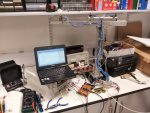
Just had a closer look at the photo of your setup.
Looks like a standard air solenoid. If yes, then the magnetic end-stop switches should be adjustable to activate and more importantly, stay activated at the end of travel. I've used many such solenoids and never had a problem setting up the switches as LIMIT switches.
 

Basrad

Member
BB - you are right, the air system is as you say, but the arm rotates aswell which are the reeds i'm refering too. I am now planning a digital encoder, or a VR sensor, and a pair of max travel mechanical break switches as also suggested..

But for now this arm is running well. I've found slowing the speed of the DC motor, and using vary to store last state and direction seems to be working very well now. Will be having a go at EEPORM writing, but that for making me aware of its limited life span.. I wonder if there are projects making use of flash RAM or usb sticks.. Should this have a longer life?
 
Top