Lego mindstorms Ultrasonic sensor

D396

Senior Member
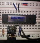
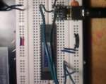
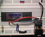
I am trying to use my NXT ultrasonic sensor with my picaxe. I am using the code and circuit in the code below but all I get is 255 for the distance. It also works fine with the NXT so the sensor is okay. Any ideas? thanks.
Code:
#picaxe 18x
' J1 External Power Fitted (4.5V)
' J2 SCL Pullup  Not fitted (pullup is in sensor)
' J3 SDA Pullup  Not fitted (pullup is in sensor)
' H2 9V Power  Fitted (9V)
' Lego Ultrasonic Sensor (part 9846)
' Note this sensor is much more difficult than the other
' Lego sensors to use. Consider using the SRF005 instead!
' You must provide both 9V and 5V supplies .
' Also i2c needs to be hacked due to a bug in the ultrasonic i2c firmware
' This means only the ultrasonic sensor can be used at once on the i2c bus
' as we are now using a non-standard i2c protocol
' We recommnd using the SRF005 instead!
 
symbol distance = b0 'distance in cm
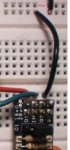
' Wires on NXT jack plug.
' Wire colours may vary. Pin 1 is always end nearest latch.
' 1 White +9V
' 2 Black 0V
' 3 Red 0V
' 4 Green +5V
' 5 Yellow SCL
' 6 Blue SDA
' Do not use i2c pullup resistor - already provided within sensor.
 
init:
 
 'Slave address is $02
 i2cslave $02, i2cslow, i2cbyte
 hi2cout $41,($02)  'continuous mode
 pause 100
main:
 
 ; read values
 ; This single line should work:
 ;hi2cin $42,(distance)
 ; but does not as dodgy firmware in ultrasonic sensor
 
 ; therefore here is the workaround
 
 hi2cout ($42)  ; address $42
 low 4   ; fake an extra pulse
 
 hi2cin  (distance) ; read distance
 
 
 ; debug display
 debug
 ; wait 1 second then loop
 pause 1000
 goto main
 

Technical

Technical Support
Staff member
Make sure you have both the 9V and 5V supplies connected, not just 5V. The code supplied was tested on a 20X2, not 18X. The extra fake pulse may not work on an 18X as it does not have the same bi-directional pin systems as the 20X2. An 18M2 may work better than 18X to fake the dodgy Lego i2c system!
 
Last edited:

Technical

Technical Support
Staff member
Same code, different chip! The problem is the 18X is always defaulting that leg to an output due to the fixed i/o layout, whereas on the 18M2/20X2 it is always bidirectional. Therefore the hack 'low 4' works internally quite differently in the different chips. You could try adding another i2cslave line after the 'low 4' hack, but we are not that hopeful!
 
Last edited:

D396

Senior Member
Ok. I don't Have one on hand though. There is absolutely no other way to do it with the 18x?
 
Last edited:

D396

Senior Member
Could Someone check my wiring for the 40x2 circuit. I got it a long time ago and It never worked so I am trying it for the first time since then. Still doesn't work.
 

Attachments

BillyGreen1973

Senior Member
Not too sure why you have two +v and two 0v connections, you only need one of each.
Also the hI2c pins are 18 and 23 (scl and sda respectively), and I dont see a connection to these pins.
The reset pin seems to be Ok and tied to +v. On the little PCB (I guess its a download circuit) I cannot see a 0v connection and also can not see where it connects on the breadboard.
I would do away with this and just use a 22k and 10k resistor to make the download circuit on the breadboard directly.
If the download circuit is not right the Picaxe will 'hang' as it thinks a new download is trying to start.
 

eclectic

Moderator
Sorry, but I find that circuit impossible to follow.

Is it possible to colour-code the wires.

1. It makes it easier for you to follow the circuit
and
2. It makes it easier for people who may try to help you.

e
 

D396

Senior Member
Sorry about that. Okay here it is.
Red = Serial in.
Green = Serial Out.
Blue = 5 Volts
Black = Ground.
The top row of each set of power buses is +5V the other is GND.
 

Attachments

D396

Senior Member
Not in the picture on the far right there is a power supply circuit and it connects the top and bottom power buses. Just to try I connecting it directly to the picaxe ground pin. Same results. No hardware found.
 

eclectic

Moderator
OK
1. Remove the 40X2

2. Plug in a known to be working Picaxe.

3. Connect the V+, Gnd, Serin, Serout wires
and the Reset resistor.

What happens?
 

D396

Senior Member
Nope. Plugged it into my breadboard the day a got it(). Didn't work. Tried twice since then and now still doesn't work. I have rewired every time tried external resonator. Nothing. Got it from tech supplies about 8 months ago.
 
Top