Maybe I could write this another way, but I thought this should work???
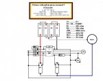
I have a day/night security camera, and if you have ever seen the images from one, you might remember the colors are not right. The only way I know to correct that is to use a filter exchanger...a little deal that moves an IR cut filter over the camera sensor in the daytime to block the IR light. Well I have one of those on this camera, and I built a little circuit to control it. All it is really, is a Picaxe 08M that turns on one of two relays for a second to switch the filters when it should. Mechanically this works great, and during the test time it works too. It even works in the main....but some time during the night, or daytime, it stops working??? I can remove power from the chip for a second and it will work just fine again.
I don't usually use gosub, but I thought it was time to learn how. If you could please take a quick look at the code, and maybe point out where I messed up, I would be in your debt...thanks in advance.
Code:
low 0   'night relay
low 1   'day relay
high 2  'CDS power
input 4 'CDS
disablebod

'b1       is light level
'b2       tells Picaxe which filter position
 b3 = 10  'test timer in seconds

pause 3000

high 0
pause 1000
low 0
b2 = 1
pause 1000
high 1
pause 1000
low 1
b2 = 0
pause 1000

switch_test:

do while b3 > 0
readadc 4,b1
if b1 =< 200 and b2 = 0 then gosub night_time
if b1 > 200 and b2 = 1 then gosub day_time
b3 = b3 - 1
pause 1000
loop
low 2
POKE $1F,0
goto main


main:

sleep 130
high 2
pause 100
readadc 4,b1
low 2
POKE $1F,0
if b1 =< 200 and b2 = 0 then gosub night_time
if b1 > 200 and b2 = 1 then gosub day_time
goto main


night_time:

high 0
pause 1000
low 0
b2 = 1
b3 = 10
return


day_time:

high 1
pause 1000
low 1
b2 = 0
b3 = 10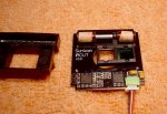
return") ) The exchanger has a coil and the filter is on a magnet, a short pulse is all that is needed to move the filter, then it just stays there till you reverse polarity and pulse it again. Here is a picture of one, but the one inside my camera now has all the control parts stripped off...long story
) The exchanger has a coil and the filter is on a magnet, a short pulse is all that is needed to move the filter, then it just stays there till you reverse polarity and pulse it again. Here is a picture of one, but the one inside my camera now has all the control parts stripped off...long story