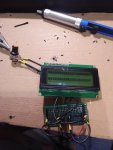
Ahem... after having managed to connect to an LCD via direct connection, I thought this'd be a piece of cake, yet here I am. Instead of "Hello 123", I'm getting two black lines. Can anyone please help?
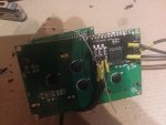
The setup: https://i.imgur.com/QMK2ngP.jpg
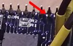
Black lines of death: https://i.imgur.com/KhtbX2z.jpg
The code is attached, copied directly from the axe131 manual. Only thing I changed was the pins.
The setup: https://i.imgur.com/QMK2ngP.jpg
Black lines of death: https://i.imgur.com/KhtbX2z.jpg
The code is attached, copied directly from the axe131 manual. Only thing I changed was the pins.
Attachments
-
168 bytes Views: 5

![20200226_115350[1].jpg](/data/attachments/19/19936-8a00d54e3672c1f837927ee6c67d1948.jpg)