LCD code or circuit problem

mickm2au

Member
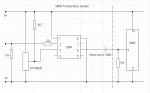
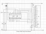
I'm have a problem with a serial LCD driver circuit and program which is a combination of ideas from the AXE 133 and Mark's LCD driver info on this forum. It comprises of a 08m reading a DS18B20 and serial out to the 18m2 driver board . The 08m circuit using Marks "serial temp to 1 decimal place" program works correctly using the commented out line of code working into a NZ LCD serial board kit I purchased. But when connected to my circuit and using the "Marks initiating code" program (with the add on' s from axe133 etc.) I get Marks intro "Axe 132Picaxe" on the second line ok, but the serial temperature data which is supposed to write to the first line comprises of wrong characters with only the tenths of degree digit showing correctly and updating with the program as written in the attachments, which is the closest to a correct display so far. I have tried different board rate and Freq settings (on both the 08m and the 18m2). I've also tried small delays in the "main" program, all giving different combinations of characters and number of characters on the screen, some changing and some times fixed. I know I can buy serial driver boards, but I wanted to design my own to help keep the brain cells active. Any ideas appreciated

The driver code...

Code:
	;Modified for my Port C 18m2 board
	;**************************


'         COMMAND SUMMARY 4 BIT MODE

'( 1) Clear Display
'( 2) Cursor Home
'( 8) Display Off
'(12) Display On/Restore Cursor Off
'(128-147) Line 1 Cursor Position 
'(192-211) Line 2 Cursor Position 
'(148-167) Line 3 Cursor Position ~ continuation of line 1
'(212-231) Line 4 Cursor Position ~ continuation of line 2
'(13) Blinking Cursor
'(14) Underline Cursor 
'(16) Move Cursor Left
'(20) Move Cursor Right
'(24) Shift Display Left
'(28) Shift Display Right

; Supported Commands

; 0-7, 8-15	CGRAM characters
; 16-252	normal ASCII characters, according to selected character map table
; 253, X	display 16 character pre-saved message from EEPROM memory, X can be 0-15
; 254, X	LCD command, X can be 0 to 255 
; 255, X	control outputs B.4,B.5,B.6,B.7 ($20 - $27)
;		So, if using a backlit LCD with the active low transistor driver
;		on output B.5, then 255,$22 switches backlight on and 255,$23 switches off


#picaxe 18m2  '  AXE132 4Bit marks

'            DB7  = C.3
'            DB6  = C.2
'            DB5  = C.1
'            DB4  = C.0

 SYMBOL RX   = B.2
 SYMBOL E    = B.0
 SYMBOL RS   = B.1
 SYMBOL senddata  = b1
 SYMBOL index     = b0
 SYMBOL estart    = b2
 SYMBOL eend      = b3
 SYMBOL baud = N2400_16
 SYMBOL line_length = 16
      SETFREQ M16
 	dirsB = %11111011
 	dirsC = %11001111
 	
 	
EEPROM $10, (" www.picaxe.com ") 	; store msg in the EEPROM memory
EEPROM $20, ("This is msg 2   ") 	; store msg in the EEPROM memory
EEPROM $30, ("This is msg 3   ") 	; store msg in the EEPROM memory
EEPROM $40, ("This is msg 4   ") 	; store msg in the EEPROM memory
EEPROM $50, ("This is msg 5   ") 	; store msg in the EEPROM memory
EEPROM $60, ("This is msg 6   ") 	; store msg in the EEPROM memory
EEPROM $70, ("This is msg 7   ") 	; store msg in the EEPROM memory
EEPROM $80, ("This is msg 8   ") 	; store msg in the EEPROM memory
EEPROM $90, ("This is msg 9   ") 	; store msg in the EEPROM memory
EEPROM $A0, ("This is msg 10  ") 	; store msg in the EEPROM memory
EEPROM $B0, ("This is msg 11  ") 	; store msg in the EEPROM memory
EEPROM $C0, ("This is msg 12  ") 	; store msg in the EEPROM memory
EEPROM $D0, ("This is msg 13  ") 	; store msg in the EEPROM memory
EEPROM $E0, ("This is msg 14  ") 	; store msg in the EEPROM memory
EEPROM $F0, ("This is msg 15  ") 	; store msg in the EEPROM memory	
 	
 	
 gosub Initialise	
 	
 Main:
 	
	serin RX,baud,senddata			; wait for the next byte

	; NB keep character mode test as first item in this list to optimise speed
	IF senddata < 253 THEN
		HIGH RS			; Character mode
		GOSUB Send  		; Send the data.
		GOTO Main			; quickly loop back to top
	ELSE IF senddata = 254 THEN
		LOW RS	     		; change to command mode for next character
		serin RX,baud,senddata	; wait for the command byte
		GOSUB Send 			; output the data
		GOTO Main			; quickly loop back to top
	ELSE IF senddata = 253 THEN
		serin RX,baud,senddata	; wait for the next byte
		GOSUB Msg			; do the 16 character message
		GOTO Main			; back to top
	ELSE 					; must be 255
		serin RX,baud,senddata	; wait for the next byte
		GOSUB Control
		
		GOTO Main			; back to top
	END IF

 
 Control:
  
   SELECT CASE senddata
   case  $20  low b.4
   case  $21 high b.4
   case  $22  low b.5
   case  $23 high b.5
   case  $24  low b.6
   case  $25 high b.6
   case  $26  low b.7
   case  $27 high b.7
   
   END SELECT
    
 RETURN
 
 Msg:
 
	LET estart = senddata & %00001111 * line_length	; EEPROM start address is 0 to 15 multiplied by 16
	LET eend = estart + line_length - 1 		; end address is start address + (line_length - 1)
	FOR index = estart to eend				; for 16 times
		READ index,senddata				; read next character from EEPROM data memory into b1
		GOSUB Send						; output the data
		
	NEXT index							; next loop
	RETURN	
 	
 	
Initialise:
 	
	FOR  index = 0 to 6                                             
          LOOKUP index, ($33,$32,$28,$0C,$01,$02,$06),senddata : GOSUB Send    ' Initialise LCD/OLED
                       '(WakeUp)*3(Set4Bit)(4Bit/2Line)(DisplayOn)(Clear Display)(Return Home)(Entry Mode Set)
 	NEXT index : PAUSE 10


Display:
            LOW  RS                                                ' commandmode
            senddata = $01 :               GOSUB Send : PAUSE 10   ' Clear Display 
            senddata = 192 :               GOSUB Send              ' (192-211) Line 2 Cursor Position

           HIGH RS                                                 ' charactermode
           FOR  index = 0 TO 12
 	        LOOKUP index,("Axe132 Picaxe"),senddata : GOSUB Send ' sending characters
	PAUSE 1000 
           NEXT index
	PAUSE 1000
	GOTO Main 

Send:

      pinsC = senddata / 16 : PULSOUT E,1 :  pinsC = senddata : PULSOUT E,1 ' 4Bitmode to LCD (14.2per second)
            
            
             RETURN
The serial temperature code...

Code:
symbol degcelraw = w3
symbol degcel = b1
symbol degceldec = b0
eeprom 0,(9,8,7,6,5,4,3,2,1,0) 'lookup table for the negitive decimals

setfreq M8

main:
readtemp12 4,degcelraw

degcel = degcelraw/16 'calculate into deg celcius
degceldec = degcelraw//16*10/16
b3 = 43 'for positive temperatures default to show a plus sign

'negitive temperature code

if degcel >= $7F then  ' if the degcel var is above 127 (max reading for +'ve is 125°C 
				;below zero "underflows" to 65535 @ -0.1 ish °C)
				
degcel = 255 - degcel 'take it from 255
b2 = degceldec
read b2, degceldec 'read the value of the decimal point from eeprom
b3 = 45 ' set b3 to show the minus character
end if
'end of negitive temperature processing

;serout 1, t4800_8, (00,192,"Temp = ",b3,#degcel,46,#degceldec,"°C") 'serial out the lot

serout 1, N2400_8, (254,128,"Temp = ",b3,#degcel,46,#degceldec,223,"C") 'serial out the lot

goto main
 

Attachments

hippy

Ex-Staff (retired)
First, try to discover if the problem is in the 08M2 code or in the modified 18M2 LCD driver code.

With the 08M2 using SERTXD ( or SEROUT to the download Serial Out pin ) does it show what would be expected to be sent to the LCD when viewed using Terminal ?

If you replace the SEROUT to LCD with some fixed data, does that display on the LCD correctly, eg;

serout 1, N2400_8, ( 254,128, "Temp = +12.34", 223, "C" )
 

mickm2au

Member
Thanks Hippy,
The 08m code works correctly into another LCD driver board I have (using the t4800 board rate which is commented out in the 08m program) and my LCD board displays correct "Axe 132 Picaxe" data (which is in the 18m2 program) but only jumbled data via serial from the 08m board.

Mick
 

mickm2au

Member
I just connected terminal to the output pin of the 08m and the correct data is displayed..

I can also send data to the LCD board using terminal ??? how do you send commands using terminal?
 
Last edited:

hippy

Ex-Staff (retired)
If using Programming Editor 6 (PE6), just enter the data to send in the "Transmit Buffer" text area exactly as you would for the corresponding SEROUT command, eg -

254,128,"Temp = +12.34",223,"C"
 

mickm2au

Member
OK...I've installed PE6 and when connected to my 18m2 input pin the correct data is displayed on the lcd using either ascii or raw. When connected to the 08m serial out pin (of my circuit) the correct data is shown on the input buffer of the terminal program. But when connected together incorrect characters appear on the lcd, although they remain constant, 4 characters, a space then 5 more characters which is a similar number of characters that should appear...temp = 23.6 (degree character)C. Could it be something to do with the pins I'm using? I picked the particular pins to enable a simpler pcb layout, so don't really want to change if I can help it. Its getting very frustrating.....The message generated by the LCD initiating part of the program appears correctly.

Mick

Edit...
Just tried heating up the ds18b20 and the 4th character in the second group which is a numerical digit changes at about the rate the tenth of degree digit would change, so it is probably correct. The second character in the second group also changes at about the rate the ten degree digit would change but is not numerical, so the positions of the characters are probably correct but only the one (tenth of degree) might be the correct character. All other characters are wrong but not changing.
 
Last edited:

mickm2au

Member
Something else I've found, if I put a pause before the "Return" at the end of the Send routine in the 18m2 program I get a different combination of characters displayed with each different pause value until with a pause greater than 280 I get no serial data at all displayed. Its as if the serout command on the 08m isn't waiting for the previous data to be processed by the serin of the 18m2 before it sends the next character thus corrupting what's received. I know that's probably not the case, but I'm running out of things to try!!
 

hippy

Ex-Staff (retired)
Execution of LCD driver code is extremely time critical. If it is not responsive then characters can be missed or misinterpreted and a corrupt display seen.

I think the problem is that your LCD driver code is simply not fast enough to be controlled by multi-character SEROUT commands from another PICAXE.

The default AXE133 firmware uses an 8-bit LCD mode and is optimised to achieve good results. By going to 4-bit mode and moving things into subroutines you have simply slowed the execution speed down too much.
 

mickm2au

Member
Thanks Hippy,

I've trimmed the code down, got rid of the send subroutines and run it at 32mhz. It now works at N4800 with splitting more complex multi character serout commands over two commands. Looks like I'll have to design an 8 bit board similar to the AXE 133 for a more versatile serial LCD driver.

Mick
 

hippy

Ex-Staff (retired)
The default AXE133 firmware is typical 'do it on the fly' output but there's no reason it has to be done that way and both LCD firmware and controlling program can be tailored to achieve the result required.

One trick is to buffer incoming data until a terminating character and then spool it out to the LCD more leisurely after that. This has a higher responsiveness when receiving data because it simply has to put data to the buffer not do more in putting that data to the display.

It will mean having a delay between display updates but it allows multi-character SEROUT transmissions and even multiple SEROUT transmissions up to the terminating character to be sent. Many programs will have delays between display updates anyway, and it's always possible to run a handshake line back to the sender so it knows if the LCD driver is ready or not for new data.

Code:
Do
  bPtr = 1
  Do
    SerIn ... , @bPtr
  Loop Until @bPtrInc = TERMINATOR
  bPtr = 1
  b0 = @bPtrInc
  Do
    If b0 = 254 Then
      b0 = @bPtrInc
      Gosub OutputLcdCommandByteFromB0
    Else
      Gosub OutputLcdDataByteFromB0
    End If
    b0 = @bPtrInc
  Loop Until b0 = TERMINATOR
Loop
 

hippy

Ex-Staff (retired)
Modified AXE133 firmware for a buffered LCD driver attached. Runs at 9600 baud and that may be its limit. Terminator of zero to indicate when buffer should be output.

Example code to drive it below ...

Code:
#Picaxe 14M2
SetFreq M8
Pause 4000
SerOut B.1, N9600_8, ( 254, $01, 0 )
Do
  Pause 2000
  SerOut B.1, N9600_8, ( 254, $80, "UUU ", #w1    )
  SerOut B.1, N9600_8, ( 254, $C0, "UUU ", #w2, 0 )
  w1 = w1 + 1
  w2 = w2 + 2
Loop
 

Attachments

mickm2au

Member
Thanks Puuhaaja & Hippy

I have looked at those threads, its where I got the idea to build my own LCD driver, and where I got part of my code from Marks threads. Lots of good info there. Just looking at Hippy's buffering idea, according to manual 2 the @ptr commands are not applicable to the 18m2 ?? although I havn't got round to trying any of the code yet. There's so many programming techniques and different ways to do stuff, every project I start I have to get my head around something new... hopefully it'll help keep dementure away....(probably spelt incorrectly).

Mick
 
Top