Dear All,
Once again I am asking for help, seems like it never ends. .. ...
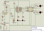
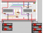
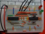
Attached is the pebbles pic of my breadboard the code and an actual shot of the breadboard.
You will notice that the code refers to pin 0,1 as this activates the LEDS, these connections are not shown in the picture as I couldnt find the icon to use.
ISSUE: Whats happening is that when I connect the motors it trips everything out. I am not sure why. Allthough the jpeg shows a 4.5 & a 6v battery attachment, I am actually using a 12v 7aH Yuasa battery that I am regualting with a 7805 chip (twice)... this gives an output on each power channel of 5.091 volts. One channel to power the picaxe and one channel to connect to pin 8 of the L293D chip. I guess in short ... I have noidea what's wrong and why it trips my circuit. Both sides of the v+ and v- are connected with jumper wire, again not shown as I could not find item in pebbles.
--------------------------
CODE
--------------------------
INIT:
symbol speedL = b1
symbol speedR = b2
let pins = %00000010 `WAIT FOR ALL CHIPS TO WARM UP
pause 1000
let pins = %00000001 `REALLY JUST A WAIT BIT TO FLASH LEDs
pause 100
let pins = %00000010
pause 200
let pins = %00000001
pause 100
let pins = %00000010
pause 200
let pins = %00000001
pause 100
let pins = %00000010
pause 200
let pins = %00000001
pause 100
let pins = %00000010
pause 200
let pins = %00000001
pause 100
let pins = %00000010
pause 1000
let pins = %00000001
`--------------
START:
gosub FRWD:
let pins = %00000010 `STOP MOTORS, RED LED ON
pause 1000
gosub BKWD:
let pins = %00000010 `STOP MOTORS, RED LED ON
pause 1000
goto START:
`----------------
FRWD:
let speedL = 150
let speedR = 150
let pins = %00110001
pulsout 6, speedL
pause 15
let pins = %11000001
pulsout 4, speedR
pause 15
let pins = %10100001 `FORWARD MOTORS, GREEN LED ON
pause 2500
RETURN
`-----------------
BKWD:
let speedL = 255
let speedR = 255
let pins = %00110001
pulsout 6, speedL
pause 15
let pins = %11000001
pulsout 4, speedR
pause 15
let pins = %01010001 `BACKWARD MOTORS, GREEN LED ON
pause 2500
RETURN
`-----------------
IC||227|270|1||U?|||PICAXE18|IC||PICAXE18_1
IC||712|270|1||U?|||L293D|IC||L293D_1
Wire||802|432|11||11|#000000|1|11|||
Wire||802|185|11||11|#000000|1|11|||
Wire||719|462|21||11|#FF0000|2|11|||
Wire||827|379|21||11|#000000|6|11|||
Resistor|10000|535|344|1|Resistor|R?||3||IC||
Resistor|1000|508|454|1|Resistor|R?||3||IC||
Wire||694|377|11||11|#999999|2|11|||
Wire||692|242|21||11|#999999|5|11|||
Wire||371|240|11||11|#999999|12|11|||
Wire||665|214|21||11|#A233C3|7|11|||
Wire||667|405|11||11|#A233C3|8|11|||
Wire||398|212|11||11|#A233C3|10|11|||
Wire||425|185|11||11|#00A060|12|11|||
Wire||452|157|11||11|#3253FF|16|11|||
Wire||721|212|11||11|#CC6633|7|11|||
Wire||719|77|21||11|#FF0000|6|11|||
Wire||827|104|21||11|#000000|5|11|||
Diode|0|776|236|1|1N4001|CR?||2|2|IC||diode_221
Diode|0|776|373|1|1N4001|CR?||2|2|IC||diode_221
Wire||263|405|11||11|#A233C3|8|11|||
Wire||477|269|21||11|#A233C3|5|11|||
Resistor|4700|211|371|1|Resistor|R?||3||IC||
Wire||290|460|11||11|#FF9900|8|11|||
Wire||533|405|11||11|#FF9900|3|11|||
Wire||531|269|21||11|#FF9900|5|11|||
Wire||587|377|11||11|#CC6633|2|11|||
Wire||585|269|21||11|#CC6633|4|11|||
Wire||344|432|11||11|#CC6633|9|11|||
Wire||342|77|21||11|#FF0000|6|11|||
Wire||207|242|21||11|#FF0000|5|11|||
Wire||209|240|11||11|#FF0000|5|11|||
Wire||342|379|21||11|#000000|6|11|||
LED|0|978|104|2|LED|LED?|2|||IC||led_22
LED|0|951|104|2|LED|LED?|1|||IC||led_12
Resistor|330|957|272|2|Resistor|R?||2||IC||
Resistor|330|984|272|2|Resistor|R?||2||IC||
Miscell||907|595|1||XX?||1|14|Miscell||misc_14
Wire||908|379|21||11|#FF0000|8|11|||
Wire||935|544|21||11|#000000|2|11|||
Miscell||206|595|1||XX?||1|13|Miscell||misc_13
Wire||234|544|21||11|#000000|2|11|||
Wire||207|516|21||11|#FF0000|3|11|||
BREADBOARDSTYLE=BB11
* (WESTAUST55, would it be possible to create another 30r, 2 Blk, Red template (for pebbles) but with a-f and g-i, or else tell me how to create the file and I will do the work and pass back for inclusion)
** Does anyone know if there is a picaxe users group in London that actually meet up for help, advice and sharing of ideas?
Once again (oo) NoIdea (oo)
Once again I am asking for help, seems like it never ends. .. ...
Attached is the pebbles pic of my breadboard the code and an actual shot of the breadboard.
You will notice that the code refers to pin 0,1 as this activates the LEDS, these connections are not shown in the picture as I couldnt find the icon to use.
ISSUE: Whats happening is that when I connect the motors it trips everything out. I am not sure why. Allthough the jpeg shows a 4.5 & a 6v battery attachment, I am actually using a 12v 7aH Yuasa battery that I am regualting with a 7805 chip (twice)... this gives an output on each power channel of 5.091 volts. One channel to power the picaxe and one channel to connect to pin 8 of the L293D chip. I guess in short ... I have noidea what's wrong and why it trips my circuit. Both sides of the v+ and v- are connected with jumper wire, again not shown as I could not find item in pebbles.
--------------------------
CODE
--------------------------
INIT:
symbol speedL = b1
symbol speedR = b2
let pins = %00000010 `WAIT FOR ALL CHIPS TO WARM UP
pause 1000
let pins = %00000001 `REALLY JUST A WAIT BIT TO FLASH LEDs
pause 100
let pins = %00000010
pause 200
let pins = %00000001
pause 100
let pins = %00000010
pause 200
let pins = %00000001
pause 100
let pins = %00000010
pause 200
let pins = %00000001
pause 100
let pins = %00000010
pause 200
let pins = %00000001
pause 100
let pins = %00000010
pause 1000
let pins = %00000001
`--------------
START:
gosub FRWD:
let pins = %00000010 `STOP MOTORS, RED LED ON
pause 1000
gosub BKWD:
let pins = %00000010 `STOP MOTORS, RED LED ON
pause 1000
goto START:
`----------------
FRWD:
let speedL = 150
let speedR = 150
let pins = %00110001
pulsout 6, speedL
pause 15
let pins = %11000001
pulsout 4, speedR
pause 15
let pins = %10100001 `FORWARD MOTORS, GREEN LED ON
pause 2500
RETURN
`-----------------
BKWD:
let speedL = 255
let speedR = 255
let pins = %00110001
pulsout 6, speedL
pause 15
let pins = %11000001
pulsout 4, speedR
pause 15
let pins = %01010001 `BACKWARD MOTORS, GREEN LED ON
pause 2500
RETURN
`-----------------
IC||227|270|1||U?|||PICAXE18|IC||PICAXE18_1
IC||712|270|1||U?|||L293D|IC||L293D_1
Wire||802|432|11||11|#000000|1|11|||
Wire||802|185|11||11|#000000|1|11|||
Wire||719|462|21||11|#FF0000|2|11|||
Wire||827|379|21||11|#000000|6|11|||
Resistor|10000|535|344|1|Resistor|R?||3||IC||
Resistor|1000|508|454|1|Resistor|R?||3||IC||
Wire||694|377|11||11|#999999|2|11|||
Wire||692|242|21||11|#999999|5|11|||
Wire||371|240|11||11|#999999|12|11|||
Wire||665|214|21||11|#A233C3|7|11|||
Wire||667|405|11||11|#A233C3|8|11|||
Wire||398|212|11||11|#A233C3|10|11|||
Wire||425|185|11||11|#00A060|12|11|||
Wire||452|157|11||11|#3253FF|16|11|||
Wire||721|212|11||11|#CC6633|7|11|||
Wire||719|77|21||11|#FF0000|6|11|||
Wire||827|104|21||11|#000000|5|11|||
Diode|0|776|236|1|1N4001|CR?||2|2|IC||diode_221
Diode|0|776|373|1|1N4001|CR?||2|2|IC||diode_221
Wire||263|405|11||11|#A233C3|8|11|||
Wire||477|269|21||11|#A233C3|5|11|||
Resistor|4700|211|371|1|Resistor|R?||3||IC||
Wire||290|460|11||11|#FF9900|8|11|||
Wire||533|405|11||11|#FF9900|3|11|||
Wire||531|269|21||11|#FF9900|5|11|||
Wire||587|377|11||11|#CC6633|2|11|||
Wire||585|269|21||11|#CC6633|4|11|||
Wire||344|432|11||11|#CC6633|9|11|||
Wire||342|77|21||11|#FF0000|6|11|||
Wire||207|242|21||11|#FF0000|5|11|||
Wire||209|240|11||11|#FF0000|5|11|||
Wire||342|379|21||11|#000000|6|11|||
LED|0|978|104|2|LED|LED?|2|||IC||led_22
LED|0|951|104|2|LED|LED?|1|||IC||led_12
Resistor|330|957|272|2|Resistor|R?||2||IC||
Resistor|330|984|272|2|Resistor|R?||2||IC||
Miscell||907|595|1||XX?||1|14|Miscell||misc_14
Wire||908|379|21||11|#FF0000|8|11|||
Wire||935|544|21||11|#000000|2|11|||
Miscell||206|595|1||XX?||1|13|Miscell||misc_13
Wire||234|544|21||11|#000000|2|11|||
Wire||207|516|21||11|#FF0000|3|11|||
BREADBOARDSTYLE=BB11
* (WESTAUST55, would it be possible to create another 30r, 2 Blk, Red template (for pebbles) but with a-f and g-i, or else tell me how to create the file and I will do the work and pass back for inclusion)
** Does anyone know if there is a picaxe users group in London that actually meet up for help, advice and sharing of ideas?
Once again (oo) NoIdea (oo)
Attachments
-
 43.9 KB Views: 59
 -
 28.9 KB Views: 55
") )
)