KS0066 LCD problem.

joeygbsn

New Member
Hi, everybody. I have been reading this forum for a while and have gotten a lot of help from it, but this is my first time that I've not been able to come up with a solution after hours of searching and trying. I am attempting to use a parallel 16x2 lcd display I bought from allelectronics a long time ago. The lcd is driven with the ks0066 chip or an equivalent. I am using a 20m2 to try and control it. I have tried many different codes posted throughout the forum and many different methods for initialization, but none seems to work completely. I can successfully initialize the display in one line mode, and write text to it, but whenever i try to switch to two line mode, the display contrast turns unreadable. All of the text is still displayed on the screen, I just can't read it unless i'm one inch from it. All other functions work well. I can turn the cursor on, blink it, and write anything I want.

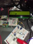
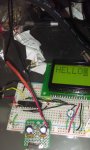
This picture is of my set up, with the display in one line mode working correctly. (sorry you probably can't check my wiring because it's a mess)
IMG_20160410_195455.jpg

And here is the data sheet that i've found for this specific module.
View attachment AC-162E.pdf

My best guess is that it has to do with the contrast pin. I have the pin connected to the wiper of a 10k pot, with one side connected to 5v and the other to ground. The contrast is only really usable when the pin is grounded through the pot. I have read about some lcds needing a negative voltage for the contrast pin, and am thinking that this could be the solution, but this doesn't really address why the contrast is readable in one line mode, and not readable in two line mode. Does the contrast pins voltage requirements change when you switch between one and two line mode?

Here is the test code I have pieced together from nick12ab's tutorial, and some others.
Code:
#picaxe 20m2
SETFREQ M8


SYMBOL  E  = C.5 `To enable pin 4 on lcd
SYMBOL RS  = C.7 `To RS pin 6 on lcd
SYMBOL lcddata    = pinsb `Port B to d0-d7

`Set pins as outputs
dirsB = %11111111
low RS
output E

pause 100
lcddata = %00110000 : pulsout E,20	`Function set: send 0x30 three times to start the module
pause 20
lcddata = %00110000 : pulsout E,20
pause 20
`lcddata = %00110000 : pulsout E,20
`pause 300
`lcddata = %00111000 : pulsout E,20 `Function set: 8 bit, 2 line , 5x8 font
`pause 200
lcddata = %00001111 : pulsout E,20 `Display on ,cursor on, blink on.					
lcddata = %00000001 : pulsout E,20			
'Clear display
lcddata = %00000110 : pulsout E,20			
'Entry mode set: Increment, cursor shift

main:
	low RS
	lcddata = 128 : pulsout E,1
	high RS
	pause 100
	lcddata = "H" : pulsout E,1
	pause 100
	lcddata = "E" : pulsout E,1
	pause 100
	lcddata = "L" : pulsout E,1
	pause 100
	lcddata = "L" : pulsout E,1
	pause 100
	lcddata = "O" : pulsout E,1
	pause 1000

	do : loop
Thanks for your time and any input.
 

inglewoodpete

Senior Member
According to the data sheet (assuming it is the correct one), you should not need an external negative voltage to set the contrast. Also, I would not expect the contrast setting needing changing when altering the LCD display mode. Perhaps it might if you were using weak batteries with the backlight on - the backlight uses 260mA.

From what you are saying, the correct text appears on the screen when using 1-line mode but things go wrong when you try to use 2-line mode - is that correct?
 

joeygbsn

New Member
Yes that is it. When i switch to two line mode the text becomes unreadable but it is in fact there if you look really hard. Unfortunately I cannot show this with a picture. I am using a lm7805 regulator as the power supply so the back light current shouldn't be a problem. The only reason i mentioned the negative voltage for contrast was because i read somewhere that is necessary some times and that grounding the pin instead can suffice. Because my contrast pin seems like it wants to be grounded for it to be readable i thought this might be the case.
 

hippy

Technical Support
Staff member
Page 13 of the datasheet indicates the initialisation sequence should be -

%00111100
%00001111
%00000001
%00000110

And there should be a delay after %00000001.

In your first initialisation bytes (%00110000) you don't appear to be setting two line mode nor setting the correct font size.

Note the "F" bit description on page 13 is incorrect; that's font size not display on/off.
 
Last edited:

joeygbsn

New Member
Power supply is a 9 volt 1 amp wall charger. I have done the initialization exactly as it states, my code is just different now from trying different things. I only started using 00110000 after seing it on other code, and that is the only success i get. If i switch to 00111000 to put it in 2 line mode the problem occurs. I think this line is commented out in my code. Also i have tried pauses between each command. I did notice that error in the datasheet. If i send 00001011 the display turns off as it should. This is my full code so far as im just testing. After modifying the axe133 firmware for a 20m2 i get the same results. If i just send 00110000 the display shows "serial lcd" or whatever on the top line. If i instead use 00111000 the problem happens. I can see the website on the bottom line but only if i look really hard.
 

hippy

Technical Support
Staff member
If i just send 00110000 the display shows "serial lcd" or whatever on the top line. If i instead use 00111000 the problem happens. I can see the website on the bottom line but only if i look really hard.
It sounds like the display multiplexing frequency or signal levels may be wrong as one would not normally see anything on the second line if it were not in two-line mode.

It may be worth contacting the supplier to see if they have any information on the issue; it could possibly be that the display is faulty.
 

joeygbsn

New Member
Im sorry for any confusion but it is in two line mode when i see things on both lines, its just that i can barely see them. But as soon as a switch to one line the text is clear as in the picture. I will probably contact the manufacturer at some point to see if maybe its the wrong data sheet, but the markings on the board seem to indicate that i have the right one. It was only $3 so no big deal. Maybe ill pick up an actual hd44780 lcd and see if i have more success.
 

inglewoodpete

Senior Member
...It was only $3 so no big deal. Maybe ill pick up an actual hd44780 lcd and see if i have more success.
There is always a risk when going down-market. I have been lucky with LCDs, although the cheapest I have tried cost me about $6.50 (gasp!). Sometimes the dollar you save costs many hours of frustration!
 

joeygbsn

New Member
Hey all just wanted to post to say that I have had success. The data sheet must be the wrong one, because the contrast pin on this board does need a negative voltage. I found a Hantronix application note regarding the generation of voltages for a lcd contrast pin.
View attachment neg-invr.pdf
The first circuit in the note is a simple charge pump circuit. I decided to construct this just to test, as I had all the parts handy, and it works. Here is a pic of my screen with both lines in use.
IMG_20160412_103310.jpg
Thank you all for your time and input. In case you are interested I don't really have a project in mind for this screen, just wanted to get it working because its been collecting dust since i bought it. I think I might make a axe133 type board with a 20m2 that I already have.
 

hippy

Technical Support
Staff member
Glad you got it sorted and thanks for letting people know.

Instead of using a separate charge pump driver you can perhaps use your PICAXE and PWMOUT to generate the square wave.
 

joeygbsn

New Member
Yeah that was my plan. Just tested it using my function generator. While im glad it works it still does confuse me that just grounding the contrast pin works in one line mode but not in two line mode. Searching through the ampire website I found http://www.ampire.com.tw/en/p1-product-detail.asp
Which says the controller is in fact the st7066-0a. Skimming through the data sheet i can't see much about the contrast. The only thing that stands out is on the last page there is a schematic and on the bottom right it shows "gnd or -V" for an input to the lcd driving voltage circuit. Is this the contrast control?
 
Top