Is my coding correct?

Prototype

New Member
Hello all,
I was wondering if anyone could give me some advice/help with my coding? I brought a beginners pic and download cable along with the download board a couple of weeks ago after a friend referred me to learn picaxe, he said it is more efficient than using unnecessary components with the bog standard timing chips. So far I have read through the whole of manual 1 and 2 (the pages that correspond to the 08m chip.) my first little project I set myself was to make a 3 letter word out of LED’s where I timed it so one letter would light up and then the second letter would light up and then the third would light up then repeat itself.

Moving more onto the point of my question, I want to make a little advance on my little project by putting it in modes. 3 mode’s if possible.

The components I am going to use are:
• A small SPST switch (push to make button)
• 08m Picaxe
• 4.5v power supply
• LED’s for the first letter
• LED’s for the second letter
• LED’s for the third letter
• A LED to show what number mode the projects in
• 330 Ohm Resistors... so the LED’s do not burn out on me ;)

The LED to show what mode my project is in will light up while in mode 1, when the project has been put in mode 2 the LED will flash twice and stay high, and when in mode 3 the LED will flash 3 times and stay high.

Here is the original code without the modes:
Code:
main:
high 0
pause 1500
high 1
pause 1500
high 2
pause 1500
low 0,1,2
pause 1500
goto main
And here is what I though the code should look like with modes:
Code:
led_for_mode_1:
high 4
if pin3 = 1 then goto mode1

Mode1:
high 0
pause 1500
high 1
pause 1500
high 2
pause 1500
low 0,1,2
pause 1500
if pin3 = 1 then goto led_for_mode_2
goto Mode1

led_for_mode_2:
high 4
pause 100
low 4 
pause 100
high 4
if pin3 = 1 then goto mode2

Mode2:
high 0
pause 500
low 0
high 1
pause 500
low 1
high 2
pause 500
low 2
if pin3 = 1 then goto led_for_mode_3
goto mode2

led_for_mode_3:
high 4
pause 100
low 4 
pause 100
high 4
pause 100
low 4 
pause 100
high 4
if pin3 = 1 then goto mode3

Mode3:
high 0,1,2
pause 250
low 0,1,2
pause 250
if pin3 = 1 then goto led_for_mode_1
goto mode3
The only problem with the code above that I have noticed is you have to hold down the push to make button and wait for it to change modes and if you hold it down for too long it goes into the next mode.
I have read up on the forum that setint with an interrupt is a good way to check for button presses, however when reading page 180+ (I think) on the setint commands I can’t seem to get my head around how I can incorporate it within my program.

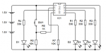
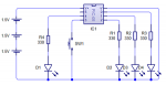
I have also attached a schematic of what my project should look like. (I have used one LED on each output on the schematic instead of using 50 :) )

Thanks for taking your time to have a look and for the reply’s if any :)
 

Attachments

Chavaquiah

Senior Member
Your code is not entirely correct but I'd say you're on the right track with the way you did you research and presented your question. :)

Oh, and BTW, Welcome!

Using an interrupt rather than expecting the user to press a button in the exact split second the code checks for it is, of course, a very good idea. This way you could use some code modularity and have basically two separate routines:
1) The main loop would flash the letters according to what mode the program is in;
2) An interrupt routine would activate as soon as the button is pressed and would take care of switching and announcing modes.

A global variable could be used to store the current mode.

As an aside, may I remind you of the usefulness of symbols? Not at all required but will make your code much easier to read and understand.

We could start of with a few definitions. This part of the code does nothing by itself, but helps writing the actual program:

Code:
'Letters
symbol LED1 = 0
symbol LED2 = 1
symbol LED3 = 2
symbol StatusLED = 4
symbol ButtonPin = pin3
symbol ButtonMask = %00001000 'Pin 3
symbol CurrentMode = b0 '(0, 1, 2) Modes numbered from zero to make the use of ON/GOSUB easier
symbol counter = b1 'Used to count the times the Mode Indicator blinks
Then, we'd better initialize a few things (including the button trigger) and start the main loop:

Code:
'The following line is just a label and not needed. It just helps document this is the initialization part
init:
   CurrentMode = 0
   low LED1, LED2, LED3
   high StatusLED
   setint ButtonMask, ButtonMask 'Interrupt on button pressed 

main:
   do
      on CurrentMode gosub Mode0, Mode1, Mode2
   loop 'Repeat forever
   'END  (Commented out as the code never reaches this point)
   
Mode0:
   high LED1
   pause 1500
   high LED2
   pause 1500
   high LED3
   pause 1500
   low LED1, LED2, LED3
   pause 1500
   return
   
Mode1:
   high LED1
   pause 500
   low LED1
   high LED2
   pause 500
   low LED2
   high LED3
   pause 500
   low LED3
   return
   
Mode2:
   high LED1, LED2, LED3
   pause 250
   low LED1, LED2, LED3
   return
All that is left now is the interrupt routine...

Code:
interrupt:
   'Code enters this routine when the button is pressed
   inc CurrentMode 'Switch to the next mode
   if CurrentMode > 2 then
      CurrentMode = 0 'Roll back from mode 2 to mode 0
   endif
   for counter = 1 to CurrentMode
      low StatusLED
      pause 100 'Perhaps too fast?
      high StatusLED
   next counter
   do loop while ButtonPin = 1 'Hold until the user releases the button
   setint ButtonMask, ButtonMask 'Reenable interrupts
   return
One more thing...

(I have used one LED on each output on the schematic instead of using 50 :) )
How do you propose to use 50 LEDs with the 08M? Make sure you are aware of the chip's current limitations... :eek:
 

Prototype

New Member
Well all I have to say is thank you very much Chavaquiah. You have given me and every one viewing that doesn’t understand a very detailed answer on how to use setint with interrupt, once again thank you! :D

Also your right it does go to show how different and easier it is to understand when using symbols. After about an hour of going through the program you have wrote and also referring to what the manual says I think I fully understand now :) after I went straight to the breadboard / testing board to see if the practical side of things worked and yes it works a treat. I would say the only problem is that because I am holding the button in my hand to press it, on the odd occasion the contact within the breadboard and between the wire off the switch are faulty. So it looks like I need to make a solid PCB up. :)

Thanks.


Prototype
 

Chavaquiah

Senior Member
Yes, about the switch - you didn't connect it like you show on your schematic, did you? Somehow a connection between a Picaxe's pin and ground doesn't look right for the code. Isn't it connected to V+ instead? And are you using a resistor to protect the Picaxe?

What about the 50 LEDs?
 

Prototype

New Member
Sorry I was exaggerating a little when I said that. I will have to find out how many LED’s the 08m can handle before they either become very dim or don’t light up at all if that is the case?
Also thank you for correcting me about the switch being connected to 0v, I have since connected it to +V. The circuit seems to have calmed down a little but every now and then when switching modes the status LED goes berserk along with the other 3 LED’s and starts flashing randomly.

+ do you mean the resistor from the serial input pin to 0V? I had forgotten to enter that into the schematic

Thanks.


Prototype
 

Chavaquiah

Senior Member
I'd have to go and check the PIC12F683 (Picaxe-08M) datasheet to be sure, but I think the maximum you can source or sink from any pin is either 20mA or 25mA. Better count on 20mA, to be safe. Depending on how efficient your LEDs are and how bright you need them to be, perhaps a couple of mA per LED might be enough. Something you'll have to test, of course, but also a limit that won't allow for too many LEDs sourced from each pin. There are plenty of workarounds, using a few extra components.

Regarding the switch, a direct connection from the battery to an input pin can be a little dangerous. If, for some reason, that pin becomes an output sinking current you'll have a short-circuit. I would suggest you use instead a circuit as shown on Manual 3 (section 3, p.25 on the latest version) so as to have a current limiting connection.
 

MPep

Senior Member
If LEDs are directly connected, the you are indeed limited to the amount of (total) current the PICAXE can supply (or source).
I would strongly suggest using a transistor to provide the drive to the LEDs, and therefore the PICAXE only requires a smal current flow. Manual 3 has the necessary circuits.
 

Prototype

New Member
Hello guy’s,

Thank you for your responses :) I think I need about 30 LED’s roughly so it looks like I am going to have to use a transistor to up the current slightly. After reading through the switch section on manual 3 I have added a 1k and 10k resistor to my switch which has been rewired. I also went out to Maplin’s to buy a better breadboard and a better SPST switch (push to make) for the my project. Once rigged up the modes cycled through nice and smoothly instead of going berserk :)

I have also attached a newer copy of the schematic as the old one was wrong (Cheers for pointing that out to me.)


Prototype
 

Attachments

westaust55

Moderator
I'd have to go and check the PIC12F683 (Picaxe-08M) datasheet to be sure, but I think the maximum you can source or sink from any pin is either 20mA or 25mA. Better count on 20mA, to be safe.
And further to the 20mA per pin, there is a limit as to the toal current each port and chip can handle.

For the PIC12F683 that is 200 mA for the entire port (all IO pins) and for the entire chip around 250 mA. With only 5 GPIO pins that become irrelevant.

Be aware that for many PICAXE chips the totals for ports and chip are as low as 95 mA.
 

Prototype

New Member
Just out of curiosity would changing the current SPST switch to a SPDT (push to make) switch be any different? When wiring?

Prototype
 

techElder

Well-known member
Prototype, the "SP" (single pole) part of the switch means that there is ONE set of independent contacts. "DP", "3P", "4P", etc. would mean there are more than one set.

The "DT" (double throw) part means that that set of contacts includes both a normally closed ("NC") and a normally open ("NO") that operate with a "throw" of the switch in either direction. Either one of them could be connected in a "momentary" fashion, too.

In your case you would just wire to the side that makes sense.

Just out of curiosity would changing the current SPST switch to a SPDT (push to make) switch be any different? When wiring?

Prototype
 

westaust55

Moderator
Just out of curiosity would changing the current SPST switch to a SPDT (push to make) switch be any different? When wiring?

Prototype
No.

Just use the NO or NC contact to common terminal as required. From your previous diagram the NO to Com contact would be used.
 
Top