IR tester - suggestions?

Man_in_uk

New Member
I am not sure on how to start this project, so I am looking for advise. This may be something that everyone already know lots about!

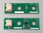
I would like to build a tester to show that an IR diode is working correctly and its it is being detected by an IR receiver. Sounds so simple. Both of these IR devices are mounted onto a machine. This device can be connected to the wire harness to prove both devices are working without removing them.
(A hand held optical tester is not suitable as there is no access to these IR devices when they are powered and working)

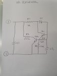
I guess I can drive the output from a PWM pin but I am not sure about measuring the signal coming back.
Can this be all done with a single 08M2 or should I use 2 chips for TX & RX?

If anyone knows of a similar project I can study, or any suggestion ... it will be much appreciated.
 

Buzby

Senior Member
You don't say if the 'wire harness' can be disconnected from the rest of the circuit, thus leaving the connections for the IR components free.

Are the IR components on a little PCB of their own, with a cable and plug which connects to a main board ?.
If this is the case then it will not be difficult to build a single PICAXE circuit to test both at the same time.

We really need a bit more info about the wiring details before we can give any specific advice.

Cheers,

Buzby
 

Man_in_uk

New Member
We really need a bit more info about the wiring details before we can give any specific advice.
Both devices are connected via a dedicated harness that terminates on a 4 pin connector. Two pins for the RX PCB and two for the TX.
TX PCB only holds a single IR transmitter. RX PCB has a simple amp circuit to boost output.
 

hippy

Technical Support
Staff member
It should be possible. If the RX PCB has an op-amp I would have thought there would be at least three wires, power supply, 0V and signal.

You can turn the TX LED on or off and then immediately check if the RX LED is on or off, do that a few times to see if it it is working.

PWM to TX would work and you could check the RX is sometimes high, sometimes low, but that could be challenging as you don't know what state the PWM is in. Get unlucky and you might miss one state entirely due to program loop and PWM timing.

Another solution would be to send a byte of serial to the TX, read that in using background serial receive from RX, then you can check that what was received was the same as what was sent.
 

Man_in_uk

New Member
The RX PCB has only 2 connections. Home made schematic attached. I went to the trouble to draw it out but I cannot say I completely understand what its doing. I have not yet had the chance to measure the voltage across either PCB in a working state but my guess is that the RX will be sinking volts to ground on getting a signal.

As you can probably tell, my experience in working with IR at this level is pretty much zero.

I do not have any manufacturer information on the components used. The supplier of the equipment will not pass on such info.
 

Attachments

kfjl

Member
Hi,

If you were to connect a picaxe input to your IR receiver's ouput, and a picaxe output to an ordinary LED (through a current-limiting resistor), you could make the LED flash when there is infrared activity using the attached program.

An IR receiver has three legs and no transistors connected to it. Are you sure your IR RX is not a TX?

#picaxe08M2
#no_data
input c.3
output c.2

main:
if pinc.3 = 0 then goto ledon
if pinc.3 = 1 then goto ledoff
pause 100
goto main

ledon:
high c.2
goto main

ledoff:
low c.2
goto main
 

Buzby

Senior Member
An IR receiver has three legs and no transistors connected to it. Are you sure your IR RX is not a TX?
An IR Receiver has three legs, but an IR Diode only has two. I think the whole device is not transmitting and receiving data, but just giving a 'blocked/unblocked' state, like a sort of photoswitch.

It would help if we knew what the function of this device was. A photo of the wiring would also be very helpful.

As hippy says, we would expect to see 3 wires if there is an op-amp, but your diagram shows only two. It looks similar to the circuit used in Namur photocells, which switches between two different currents depending on the IR Diode state.

If it is a two-wire circuit we need a bit more info to get any further, specifically the currents drawn in both the On and Off states.
 

hippy

Technical Support
Staff member
Analogue is not my thing but I would imagine an active two-wire receiver is intended to be used with a pull-up so it effectively acts like a switch, pulling down towards 0V when activated.

Can you supply any details on the equipment being used ?
 

Buzby

Senior Member
... I would imagine an active two-wire receiver is intended to be used with a pull-up so it effectively acts like a switch, pulling down towards 0V when activated.
It might be just that. The Namur devices are wired to an active equivalent of a pull up resistor, but this 'resistor' can detect open circuit and short circuit conditions, as well as on/off, by monitoring the current. Systems that use modules with mutiple Namur sensors can even detect cross-wired or shorts across circuits. They are one of the elements of highly safety critical control systems.

I don't think this device is Namur, but just an active two-wire sensor, as you described.

A picture, and a description of the application, will give us a lot more to go on.
 

Man_in_uk

New Member
Still not been able to to take any reading from these while in use, as I do not have easy access to them(located in another part of the country).
Pictures attached of the devices in question.
 

Attachments

Buzby

Senior Member
Do you have these parts in your possession ?

If so, it should be easy to find their characteristics.

The TX looks like its just a LED, so 5v and 470R should light it up. Use a mobile phone as a camera to view the LED activity.

The RX is a bit more complex to work with. I would use another 5v/470R combination to power it, and measure the voltage dropped acrossed the board. It should vary with light from the LED.

It might take a bit of trial and error, but once we know the characteristics it will be easy to design a tester based on a PICAXE.

Do you have some matching connectors to connect to these boards ?

Cheers,

Buzby
 

Man_in_uk

New Member
Do you have these parts in your possession ?
For me, step one is always to get my hands on the stuff. The parts shown in the pictures are on my bench and I also ordered the correct connectors for them.

I now realise from reading all the replies to my help request that I do not have enough information. I feel it would be wise to take a trip to a working installation and take some simple readings from these things in use.

I like the idea of 5v and 470R but before I do that, I will check what the manufacturer is putting into it.


I do appreciate everyone's suggestions and I am very happy for the help. Let me come back in a few days once I have used a meter on these.
 

Man_in_uk

New Member
I have some numbers and a huge gap in my understanding of IR!

The controller is putting out to the TX PCB 2.2v square wave at 1Khz.
The RX PCB is measuring 17v. This voltage is being sourced to zero when the signal is present.

It would seem that (as suggested earlier) sending a signal to the TX will cause the RX to sink a signal to 0. But now my lack of understanding comes into play.
Why use a 1Khz wave?
Does this mean I have to build a tester that can identify the wave coming back?
 

Buzby

Senior Member
In it's normal application is this device exposed to ambient light ? If so, the 1Khz could be to overcome background illumination.

Regarding testing with a PICAXE, just an on/off detection is needed. If the PICAXE switches the TX at, say 1hz, then the PICAXE can detect the RX signal and drive a simple LED. This will be easy to see by eye.

If the TX frequency is increased to 1Khz then the RXed signal will need to be compared with the TX using software, still not difficult to do.

One thing that is unclear so far, do you want a PICAXE circuit to test the RX and TX boards independantly, or always together as a pair ?.
 

hippy

Technical Support
Staff member
Why use a 1Khz wave?
It could be to ensure reliability which would be important in a safety critical system. By toggling the output and checking what comes back one can judge that everything is working. If what comes back is permanently high or low when it should be toggling then a fault condition can be determined and appropriate action taken.

As to why 1kHz; that could have simply been an arbitrary choice or perhaps related to the way the RX circuit functions.

Does this mean I have to build a tester that can identify the wave coming back?
In so far as it having to check it's not present when it shouldn't be and is when it should be., or you won't be able to detect stuck high and suck low faults., it won't be much of a tester.
 

Man_in_uk

New Member
One thing that is unclear so far, do you want a PICAXE circuit to test the RX and TX boards independantly, or always together as a pair ?.
Very good question. Always as a pair.
Presently the only option to repair or diagnose a fault on this sensor pair is to remove a large assembly to get access. At this point the technician usually replaces both PCB's before installing and testing to see if the fault remains. If the fault is a bad wire in the harness, the fault remains and the large assembly has to be removed again.
The tester I would like to build would allow the technician to check the harness and both PCB's are working while the assembly is still removed.
 

Man_in_uk

New Member
Just to get started, I am trying to build a circuit that drives the IR diode in exactly the same way as the original controller. Then worry about the testing the RX later on.
I took two volt readings on the wires running to the two pins on the TX PCB. Fluke multimeter reads 2.6v DC, Picoscope reads 2.2v square wave @ 1KHZ.

At present I have only got up to 1.5v with 68ma across the diode using a 32 ohm resistor.

Due to the current required, I do not think it is possible to use the PIC chip directly to switch this part. I have tried to bridge multiple pin togethers as a single output, but as the software is turning them on in sequence I am not getting a true square wave output.


Can you suggest a circuit I should be using to drive this diode at around 100ma?


Thanks
 

Buzby

Senior Member
100mA seems a lot for that LED !.

I would set the PICAXE to a very slow squarewave, 5s on / 5s off. Use a 470R series resistor to start with. Then put the Fluke in series to measure current.
With the slow rate the meter will have time to stabilise, and you can read the actual current. ( Trying to measure anything in the kHz range with a meter is always dodgy, no matter what the spec of the meter says !. )

Reduce the 470R until current reaches about 20mA. Check IR output with mobile phone camera.

Once we've got the TX working we can move onto slow-speed RX.
 

Man_in_uk

New Member
100mA seems a lot for that LED !.
I agree. At present if I use a cycle of 5s on / 5s off is it running at 1.7v @ 80ma. It is working and I can get the RX PCB to react.
My worry is ......... if I am not driving it at the same voltage as the original controller, is my tester not giving it a real world signal to measure?

UPDATE.
on my test setup, I have the RX PCB as follows. Pin 1 = 10k resistor to 5V. Pin 2 = ground.
If I drive the diode as above using a 33 ohm resistor at 1.7V, the RX PCB will sink the 5v down to 0.8v when activated.
If I lower the current with a 390 resistor I am driving with 1.2v @ 10ma. At this setting the RX PCB does not react at all.
 
Last edited:

Man_in_uk

New Member
A very different question, if I may?

I have got this circuit as simple as I think I can, using only 6 components.

I would like to build a few of these using SMD components but do not want to add a programming jack & associated resistors to each one. Is there a recognised way of pre-programming an SMD IC before soldering or making some sort of JTAG type adaptor?
 

hippy

Technical Support
Staff member
Recommended practice would be to take the Serial In and Serial Out signals to the external connector -
Code:
     |---.
  V+ | O-|-----------.
     |   |   .-------|--------------------.
< TX | O-|---'       |    .----_----.     |
     |   |           `----| V+   0V |--.  |
> RX | O-|-----------.--->| SI   SO |--|--'
     |   |          .|.   |         |  |
  0V | O-|---.  10K |_|   `---------'  |
     |   |   |       |                 |
  0V | O-|---^-------^-----------------'
     |---'
Alternatively TX, RX and 0V can be taken to the unpopulated holes of a three-way header -
Code:
     |---.
  V+ | O-|-----------.
     |---'   .-------|--------------------.
     |       |       |    .----_----.     |
< TX |   o---'       `----| V+   0V |--.  |
> RX |   o-----------.--->| SI   SO |--|--'
  0V |   o---.      .|.   |         |  |
     |       |  10K |_|   `---------'  |
     |---.   |       |                 |
  0V | O-|---^-------^-----------------'
     |---'
Your JTAG-like adapter can then simply be a jack socket with flying wires or wired to a three-pin header. The header can usually be held in the holes with a tilt applied while downloading takes place.

A single 10K can be used on the Serial In line to keep the PICAXE from inadvertently entering its downloader mode while an AXE027 will override that when a download is required.
 

Man_in_uk

New Member
Just when I thought things were going in the right direction ............................

I can find a nice selection of handheld plastic cases that include a battery compartment, but only hold 2 x AA or a 9v PP3.
The paperwork that came with my Picaxe starter kit states that a PP3 should not be used.

If I plug a PP3 into the volt reg. on my project board, the tester circuit appears to still work correctly. Is this information old news or should I avoid the PP3?
 

Man_in_uk

New Member
Thank you for your advise.

Does anyone know of a source of handheld cases that have battery compartments that hold a suitable amount of AA batteries?
 

Buzby

Senior Member
I've got this sloped-front enclosure, with a 5 x AA battery box built in.

Can't remember where it's from, but its made by OKW.


I think I got this free as a sample !


okw1.pngokw2.png
 
Last edited:

Buzby

Senior Member
Have you determined exactly what voltages you need ?.

The PICAXE can run at 3v, but the rest of the circuit may need 9v or 12v, or maybe more.

As your device is only used for short periods at infrequent intervals, a step-up boost module would be a good solution.

This method would let you use a two-cell box, which means it can be quite small.
 

Man_in_uk

New Member
Have you determined exactly what voltages you need ?.
I have been playing around to see what I can & cant get away with. After finding a document that told me only the X2 versions are suitable to run at 3.3 volts, I then gave up experimenting with 3 volts.
I can get my circuit to run at 3v but this was not enough power to allow the computer to see it. The Picaxe editor gave me an error when trying to download a program.

Although its not recommended, I have stuck with a PP3 for now. I am currently testing to see what sort of battery life I should get out of a PP3. This device should only need to be used for 10 seconds a time. It will either show a pass or fail, so I should get a reasonable battery life.

On a separate subject. Is there an in circuit emulator for these chips?
I am using the ADC to measure voltage and having a value shown to me would make life easier.
 

hippy

Technical Support
Staff member
On a separate subject. Is there an in circuit emulator for these chips?
I am using the ADC to measure voltage and having a value shown to me would make life easier.
The usual approach is to keep the tester connected via the AXE027, add SERTXD commands to your code, then open the Terminal window from within PE6 (F8 function key) to show what is being sent by those SERTXD commands. Something like ...
Code:
#Picaxe 08M2
#Terminal 4800
Do
  ReadAdc C.1, b0
  SerTxd("ADC from C.1 = ", #b0, CR, LF)
  Pause 1000
Loop
Use '#Terminal 9600' for X2 chips.
 

Buzby

Senior Member
I'm not sure why you are using ADC. The function of the system is just a binary on/off, running at 1Khz.

So your code would need to do something like this :

' Test part 1
Turn LED on
pause 500uS
If RX is Low then set Result1 to Pass, else set Result1 to Fail
'Test part 2
Turn LED off
pause 500uS
If RX is High then set Result2 to Pass, else set Result2 to Fail
' Combine test results
If Result1 = Pass and Result2 = Pass then set Result3 = Pass, else set Result3 = Fail
' Drive result LED
ResultLED = Result3
repeat

One other point, I seem to remember you posting that the RX board is fed with 17v, and this drops to nearly 0v when the RX is activated.
Your 5v/10K to pin 1 of the RX may not be providing enough current for the RX circuit to work properly. I would suggest raising the supply to at least 9v ( which you already have, although I would prefer 15v ) and reducing the resistor to 1K. This would give the RX board something in the region of 10 to 15mA, which should be enough.
 

Man_in_uk

New Member
I'm not sure why you are using ADC.
Thank you for the suggestion. Your code looks so simple compared to mine, although I use the flowchart method.
(yes, I am the one who cant be bothered to learn the real way of programming)

I am using the ADC for two different functions. The first being a battery level indicator.

You are correct that the RX PCB has the ability to source 24v to 0 when you give it a good dose of IR. Here is the problem ..... the original manufacturer is driving the IR LED very hot. I have not been brave enough to put 2.2v into the IR LED, I am only driving it at 1.7v via 33ohm resistor. That gives it 80ma.
Using the 1.7v does not give the RX PCB enough light to source my 5v down to 0, so I have setup an ADC to determine if the RX is doing something. I think the RX drops my 5v rail down to around 2v.

I would have liked to drive both PCB's at the correct voltages but wanted a small portable device. Although its far from perfect, it does indicate if there is a fault.
 

hippy

Technical Support
Staff member
Although its far from perfect, it does indicate if there is a fault.
But does it ? What you are testing is whether it works under the conditions of your testing which it seems are rather different to what the conditions will be when it is actually in service.

I am happy to accept that testing under test conditions can be good enough to say things should be okay under in-service conditions but it seems you are having to contrive a test to determine a pass. Whether that's legitimate in this case I don't know.

I can understand the desire for a small hand-held unit but that seems to be putting ergonomics ahead of the core requirement of being able to accurately and reliably test the transmitter and receivers in-situ. Would it really be problematic if the tester were a briefcase or make-up box affair ?

I would suggest the best approach would be to determine what is needed to test the transmitter and receiver, what circuitry, voltage and currents, are required to undertake such testing, then worry over how that can be packaged or optimised to fit into a smaller unit once that's all proven to work.
 

hippy

Technical Support
Staff member
If we take a step back to check what we are trying to do, from what I can tell, this is what we have, need to achieve through testing -
Code:
                 ............................     .........
        ___      :  X       __              :     :       :
Vrx >--|___|--.--:--.---.--|__|--.          :     :   .---:--< +
        Rrx   |  :  |  .|.       |          :     :   |   :
              |  :  |  | |    .--^--.       :     :   |   :
              |  :  |  |_|    |     |---.   :     :   |   :
Vin <---------'  :  |   |     |     |  _|_  :     :  _|_  :
                 : _|_   \ |  |     | _\ /_ : <-- : _\ /_ :
                 : -.-    >|--|     |   |   :     :   |   :
                 :  |    / |  |     |---'   :     :   |   :
                 :  |   |     `--.--'       :     :   |   :
                 :  |   |        |          :     :   |   :
0V --------------:--^---^--------'          :     :   `---:--< -
                 :..........................:     :.......:
The key things to me are what the signals are for a live in-service system, what voltage is applied across '+' and '-' on the LED, what signal can be observed at 'X' on the receiver, what will be our 'Vin'.

The voltage across the LED appears to be 2.2V at 1kHz which seems fair enough, not beyond what might be anticipated. That 2.2V may be higher than the LED Vfwd but it is a 1kHz signal which presumably keeps averaged heating effect within acceptable limits.

What the signal is at 'X' seems to be the current unknown, and that is essential for testing. I expect it's at some voltage when the LED is disconnected, dropping to some other voltage but not reaching 0V when the LED is connected and lit.

The other unknown is what testing circuit you are currently using ?

I have no idea what value 'Rrx' should be in the above but expect 'Vrx' can be 5V and perhaps less, and that the LED can be driven from 5V or less with a suitable current limiting resistor via PWM.

My first attempt at a PICAXE test circuit would likely be something like -
Code:
       .-------------------------------------.
       |   ___        .......... ..........  |
 5V >--^--|___|--.----:-O X    : :    + O-:--'
           Rrx   |    :        : :        :
ADC <------------' .--:-O 0V   : :    - O-:--.
           ___     |  :........: :........:  |
PWM >--.--|___|----|-------------------------'
       |   Rtx     |
SYN <--'           |
                   |
 0V ---------------'
That 'SYN' is just so the PICAXE can tell whether the LED is on or off. It might be possible to read the PWM pin itself to avoid having an additional pin. One would have to test that.

Then it's just a case of looking for that 'SYN' to go high or low, reading the ADC and checking it is as expected. If not something has failed, otherwise it passed.

It should continually pass until the LED is disconnected and then it should fail.

If that works I would reduce the 5V to see how low it can go before it starts failing when it should pass. One will probably need to adjust the two R and expected ADC values as the voltage is reduced.

But note this is only a test to 'check the LED lights and the receiver detects that' test. It may be that in live in-service equipment the LED doesn't light enough for the receiver to produce the voltage the equipment expects. One would have to more accurately emulate the in-service equipment to have a more comprehensive test.
 
Top