IR remote reader: get the code! :P HELP!

macsoft

Member
Hi!
I really love these little chips, and I've done lots of simple circuits with them like little simple robots, and circuits to control my automatic blinds, and other simple home automation stuff. But i really dont have a lot of electronics knowledge. I can hook up a chip to a base circuit, and control inputs and outputs, and not much more then that.

PROJECT: I have a simple circuit based on the 08m2 that triggers a simple IR camera remote.
What it does is at my command an output is high, and the output powers the camera remote directly (amped by a BC550 transistor).
What I would like to do is to not need to add the camera remote in the circuit. I would like to attach an IR led to my 08m2 and for it to send the signal directly to my camera.
Problems: it is a sony camera, but it does not seam react to the picaxe sony TV codes, but as other sony ir codes it should be slow enough for the picaxe to be able to reproduce it, no? I've tried a program that cycles all IR TV codes of the picaxe with no success finding one that triggers the camera.

FIRST: how hard would it be to do a circuit to read the IR code on the remote and then transfer that code to another circuit that reproduces it like a simple remote?
It would be best to have one circuit to read the IR code from the real remote, that i could somehow store in the computer (?) and download on to my circuit that triggers the camera.
And if the 08M2 cannot do it alone, what would be the simplest circuit with addons that could do it?
thank you very much you electro gurus!! :p.
 

bgrabowski

Senior Member
Yes that's the one. Read it to the end as it was ultimately successful. You then need to Google Canon and Sony protocols to establish that they are the same.
 

boriz

Senior Member
An IR control signal is usually just a series of high-low pulses with precise intervals. A Picaxe should have no problem replicating most protocols. All you need is a good definition of the signal you want to reproduce. The easy way is to examine the signal on a digital storage 'scope and measure the number and duration of the pulses.

Often a code pattern will consist of a long pulse for 1 and a short pulse for 0 with a longer start pulse, or something like that. The pulse durations are usually well within Picaxe speed limits.

You also need to add a carrier, but that's also easy for a Picaxe.

Do you have a 'scope?
 

geoff07

Senior Member
I use some working code that drives a Nikon camera, not my original code - found elsewhere on the forum a few years ago - but it does work fine and should help you get started once you have the scope trace to copy.
Code:
take_shot_nikon_ML_L3: 
{     high HO_red_led: pause 1000 
      low HO_red_led  
'http://www.picaxeforum.co.uk/archive/index.php/t-10448.html 
      low HO_IR_sender ;LED OFF 
      pwmout HO_IR_pwm , 51, 104 ; 38400 from wizard 
      for B_IR_loop = 1 to 5 
         pulsout HO_IR_sender,400 ; ON 2000uS 
         pause 56 ;off 28 mS 
         pulsout HO_IR_sender,77 ;ON ~390 uS 
         pause 3; off 1.5 mS  
         pulsout HO_IR_sender,82 ; ON 410 uS 
         pause 7 ; off 3.5 mS 
         pulsout HO_IR_sender,80 ;ON 400 uS 
         pause 100 ;off 50 mS (or 63ms?=pause 126) 
         if F_handle_remote = C_true then 'any key interrupt 
            return 
         endif 
      next 
      pwmout HO_IR_pwm, off 
      high HO_red_led: pause 2000 
      low HO_red_led 
}     return
This runs in a 18M2 at 8MHz.
 

macsoft

Member
Hum.. trying this code on my 08M2 gives my this first compilation error: "pwmount HO_IR_pwm , 51, 104 ERROR: This command requires the pin number in format PORT.PIN not PINx" :S
 

inglewoodpete

Senior Member
Hum.. trying this code on my 08M2 gives my this first compilation error: "pwmount HO_IR_pwm , 51, 104 ERROR: This command requires the pin number in format PORT.PIN not PINx" :S
This should not be a problem but you need to design for circuit around the 08M2. What pin are you using (or planning to use) for PWM? Refer to Manual 1 for pin functions on the various models of PICAXE.
 

macsoft

Member
hum.. i'm just testing around and trying to understand the code, it seams that there is no error if i use HO_IR_pwm=2.
where does the ir led goes? HO_IR_pwm or HO_IR_sender?

I've tried the code with these values:
symbol HO_red_led=0
symbol HO_IR_sender=2
symbol HO_IR_pwm=2
symbol B_IR_loop =b1

And it does accept the code (minus the any key interrupt part but i think that is more to do with when to stop it right? i just deleted that part for a continuos test sending)
I still need to understand the difference between symbol HO_IR_sender and symbol HO_IR_pwm. can you please explain?
Thank you :)
 

inglewoodpete

Senior Member
The I/O connections will depend on your circuit. I presume you haven't yet made those decisions. I'm not familiar with the detail of the original project, which was a thread of over 70 posts!

Can you post a copy of the circuit from the original project on your thread so that we can get a better idea of what is needed?
 

macsoft

Member
I have a simple PCB board made to house a 08M2 and same basic download circuit. my main question is: where does the IR led goes? HO_IR_sender or symbol HO_IR_pwm? It seams logic to go to HO_IR_sender. but then what is symbol HO_IR_pwm for?
I've been trying to read the hole post on this, but it is getting complicated to understand most of it.
puting the IR led on HO_IR_sender, i can make it blink fast like the cameras remote does.. but i keep wondering what does HO_IR_pwm do? do i stick another IR led on it?
(i dont have a nikon camera to test, but when i have a working circuit i will go to my friends house to test it)
thank you
 
Last edited:

hippy

Ex-Staff (retired)
my main question is: where does the IR led goes? HO_IR_sender or symbol HO_IR_pwm?
Though I have not looked at the earlier project I would guess the answer is "between the two". It is most likely that the PWM provides the carrier, the other signal provides the modulation effectively turning the LED on and off.
 

macsoft

Member
Though I have not looked at the earlier project I would guess the answer is "between the two". It is most likely that the PWM provides the carrier, the other signal provides the modulation effectively turning the LED on and off.
Hum..I've just tried it, and putting a led between them (positive pole on symbol HO_IR_pwm, negative on HO_IR_sender) does make the LED blink. Could this be it?
if this is the solution then it will get a lot complicated to get the modulation on my sony remote.. because i do not understand the way it works :S
I'll take this to my friends house with a nikon and see if that works.
Thank you!
 

geoff07

Senior Member
Just to clarify my terminology:

HO_ = hardware output
HI_ = hardware input
B_ byte; F_ flag; W_ word; C_ constant etc. You get the idea. It helps when reading the code after a year or two (which applies in this case)

If your friend with a Nikon uses an ML-L3 remote thingy or his camera is compatible with it (I think many are) then it should work fine assuming you were able to fit the code to the pins etc.
 

macsoft

Member
Hello Geoff thank for the clarification.
Can you confirm that the IR led is between the two? positive pole on symbol HO_IR_pwm, negative on HO_IR_sender?
thanks!
 

macsoft

Member
Oj i finally got one of those pocket oscilouscope.
I'm trying to learn how to use it to read the signal on my remote.
I hooked up the probes to the IR led connectors, and I can see some kind of a wave.
What is next?! :p
please help a newbie :)
 

inglewoodpete

Senior Member
It's been a while. Can you refresh the details for us?

Are you using the oscilloscope on a commercially remote handpiece? Or are you displaying the output of your PICAXE-based circuit? I know that you are new to this but it is not clear to me what you are trying to do. Your plan is to use a PICAXE circuit to send IR to ?what model device?
 

macsoft

Member
Hi there.
My plan is to get a picaxe 08M2 to emit IR signal to trigger my sony camera.
I'm reading signals from a commercial remote that works with my camera.
 

macsoft

Member
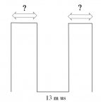
So here is what i gather: the remote emmits a square wave of 16 pulses 13us apart. then it waits about 640us before it repeats the wave.
While in the 16 pulses repetition the wave is between 760mV to 1.31 V. it drops to 0Volts while it pauses for 640us.
Now.. I can get my 08M2 to do this? :S
 

eclectic

Moderator
So here is what i gather: the remote emmits a square wave of 16 pulses 13us apart. then it waits about 640us before it repeats the wave.
While in the 16 pulses repetition the wave is between 760mV to 1.31 V. it drops to 0Volts while it pauses for 640us.
Now.. I can get my 08M2 to do this? :S
What is the pulsewidth?

Is it always the same?

Does it change?

Can you post a good picture or photograph of the Oscilloscope trace?

e
 

Attachments

macsoft

Member
Hello ecletic thank you for your patience
here are two pics. its a patterns that repeats 16 times where the wave is between 680mVolts to 1.29 Volts, then drops to 0 volts for about 640us,
can you help my how i can reproduce this with a 08M2?
thanks in advance :)


inglewoodpete

Senior Member
OK. That is displaying the 38 to 40kHz carrier signal. We now need you to "zoom out" so that the bursts appear as blocks across the screen.

Refer to the yellow trace on the oscilloscope traces i posted here (post #1). Note that my traces are the demodulated signal (38kHz carrier removed).
 

macsoft

Member
Ok I just found some Arduino code that has exactly the IR pulse I need.
I just need help to converting it to PICAXE basic to make it work.
Can someone help me on this?
Here is the arduino code :

Code:
void pulseON(int pulseTime) {
  unsigned long endPulse = micros() + pulseTime;        // create the microseconds to pulse for
  while( micros() < endPulse) {
    digitalWrite(pinIRLED, HIGH);                       // turn IR on
    delayMicroseconds(13);                              // half the clock cycle for 38Khz - e.g. the 'on' part of our wave
    digitalWrite(pinIRLED, LOW);                        // turn IR off
    delayMicroseconds(13);                              // delay for the other half of the cycle to generate wave/ oscillation
  }
}
void pulseOFF(unsigned long startDelay) {
  unsigned long endDelay = micros() + startDelay;       // create the microseconds to delay for
  while(micros() < endDelay);
}
void takePicture() {
  for (int i=0; i < 2; i++) {    // impulse send twice
    pulseON(2336);
    pulseOFF(646);
    pulseON(1168);
    pulseOFF(621);
    pulseON(572);
    pulseOFF(621);
    pulseON(1168);
    pulseOFF(621);
    pulseON(1168);
    pulseOFF(621);
    pulseON(572);
    pulseOFF(621);
    pulseON(1168);
    pulseOFF(621);
    pulseON(572);
    pulseOFF(646);
    pulseON(572);
    pulseOFF(621);
    pulseON(1168);
    pulseOFF(621);
    pulseON(572);
    pulseOFF(621);
    pulseON(1168);
    pulseOFF(621);
    pulseON(1168);
    pulseOFF(621);
    pulseON(1168);
    pulseOFF(621);
    pulseON(572);
    pulseOFF(621);
    pulseON(572);
    pulseOFF(646);
    pulseON(572);
    pulseOFF(621);
    pulseON(1168);
    pulseOFF(621);
    pulseON(1168);
    pulseOFF(621);
    pulseON(1168);
    pulseOFF(621);
    pulseON(1168);
    pulseOFF(11008);
    pulseON(2336);
    pulseOFF(621);
    pulseON(1168);
    pulseOFF(621);
    pulseON(572);
    pulseOFF(621);
    pulseON(1168);
    pulseOFF(621);
    pulseON(1168);
    pulseOFF(621);
    pulseON(572);
    pulseOFF(621);
    pulseON(1168);
    pulseOFF(621);
    pulseON(572);
    pulseOFF(646);
    pulseON(572);
    pulseOFF(621);
    pulseON(1168);
    pulseOFF(621);
    pulseON(572);
    pulseOFF(621);
    pulseON(1168);
    pulseOFF(621);
    pulseON(1168);
    pulseOFF(621);
    pulseON(1168);
    pulseOFF(621);
    pulseON(572);
    pulseOFF(621);
    pulseON(572);
    pulseOFF(646);
    pulseON(572);
    pulseOFF(621);
    pulseON(1168);
    pulseOFF(621);
    pulseON(1168);
    pulseOFF(621);
    pulseON(1168);
    pulseOFF(621);
    pulseON(1168);
    pulseOFF(11008);
    pulseON(2336);
    pulseOFF(621);
    pulseON(1168);
    pulseOFF(621);
    pulseON(572);
    pulseOFF(621);
    pulseON(1168);
    pulseOFF(621);
    pulseON(1168);
    pulseOFF(621);
    pulseON(572);
    pulseOFF(621);
    pulseON(1168);
    pulseOFF(621);
    pulseON(572);
    pulseOFF(646);
    pulseON(572);
    pulseOFF(621);
    pulseON(1168);
    pulseOFF(621);
    pulseON(572);
    pulseOFF(621);
    pulseON(1168);
    pulseOFF(621);
    pulseON(1168);
    pulseOFF(621);
    pulseON(1093);
    pulseOFF(696);
    pulseON(572);
    pulseOFF(621);
    pulseON(572);
    pulseOFF(621);
    pulseON(572);
    pulseOFF(621);
    pulseON(572);
    pulseOFF(1218);
    pulseON(497);
    pulseOFF(1292);
    pulseON(422);
    pulseOFF(1367);
    pulseON(373);
    pulseOFF(11803);
    pulseON(298);
    pulseOFF(2659);
    pulseON(199);
    pulseOFF(1590);
    pulseON(174);
    pulseOFF(1019);
    pulseON(174);
    pulseOFF(1615);
    pulseON(174);
    pulseOFF(1615);
    pulseON(149);
    pulseOFF(1044);
    pulseON(149);
    pulseOFF(1640);
    pulseON(124);
    pulseOFF(1093);
    pulseON(149);
    pulseOFF(1044);
    pulseON(124);
    pulseOFF(1665);
    pulseON(124);
    pulseOFF(1068);
    pulseON(124);
    pulseOFF(1665);
    pulseON(99);
    pulseOFF(1690);
    pulseON(99);
    pulseOFF(1690);
    pulseON(99);
    pulseOFF(1093);
    pulseON(99);
    pulseOFF(1118);
    pulseON(99);
    pulseOFF(1093);
    pulseON(99);
    pulseOFF(1690);
    pulseON(99);
    pulseOFF(1690);
    pulseON(75);
    pulseOFF(1715);
    pulseON(75);
    pulseOFF(12101);
    pulseON(149);
    pulseOFF(2833);
    pulseON(75);
    pulseOFF(1715);
    pulseON(75);
    pulseOFF(1118);
    pulseON(75);
    pulseOFF(1715);
    pulseON(75);
    pulseOFF(1715);
    pulseON(75);
    pulseOFF(1118);
    pulseON(75);
    pulseOFF(1715);
    pulseON(75);
    pulseOFF(1118);
    pulseON(99);
    pulseOFF(1093);
    pulseON(99);
    pulseOFF(1690);
    pulseON(99);
    pulseOFF(1093);
    pulseON(99);
    pulseOFF(1690);
    pulseON(99);
    pulseOFF(1690);
    pulseON(99);
    pulseOFF(1690);
    pulseON(99);
    pulseOFF(1093);
    pulseON(99);
    pulseOFF(1118);
    pulseON(99);
    pulseOFF(1093);
    pulseON(99);
    pulseOFF(1690);
    pulseON(99);
    pulseOFF(1690);
    pulseON(99);
    pulseOFF(1690);
    pulseON(99);
    pulseOFF(646);
  } 
}
 

inglewoodpete

Senior Member
A few points:

First, a question: am I correct in assuming that you are using a phototransistor as the receiver? The oscilloscope pictures suggest this.

The oscilloscope traces in post #27 show bursts of 38kHz pulses that differ in width: some wide, some narrow. Do you know the pattern that you need?

The Pause and PauseuS are the equivalent of the delayMicroseconds() command. However, I think a better solution whould be to use the PulsOut command.

Timing on the PICAXE depends on the clock speed you are using. The default speed for the 08M2 is 4MHz. So PulsOut pin, 1 outputs a 10uS pulse on your selected pin at 4MHz clock. That will be too granular (Eg 10, 20, 30 uS) for your application, requiring a 13uS pulse.

If you run the 08M2 at 16MHz, the granularity drops to 2.5uS. So PulsOut pin, 5 at 16MHz will give you a 12.5uS pulse - probably good enough.

So, the major commands that you need to know about are the SetFreq, PWMOut and PulsOut.
 

macsoft

Member
Hi Pete,
Thank you for your ideas. I will certanly try your sugestions.
about the phototransistor, nope, i'm just connecting the probe to the IR leds pins.
 

hippy

Ex-Staff (retired)
Ok I just found some Arduino code that has exactly the IR pulse I need.
Do you have a link to where you found that which might have further information and could save yourself or others some effort ?

It looks like that code generates multiple protocol commands, 20-bit SIRC first by the looks of things but I didn't check further, so it's likely that not all are needed for your camera. On which point; have you told us what camera that is ?
 

geoff07

Senior Member
I posted the code for a Nikon camera a short while ago. It looks as though you could use that and adjust the timings. I don't have it to hand but I expect you could find it in the forum.
 
Top