Idea: control multiple leds via 2 pwm channels

juve021

Member
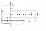
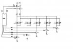
Hi all, wondering if you could give me your advice. I found this circuit on an atmega forum, tweaked it a bit but was wondering if this would work using an 18M2. I'm trying to pwm control multiple 12v led strips (each rated at typ. 90ma) using the limited 2 pwms channels on the PICAXE. Code would be pretty straight fwd looking at the circuit, set pwm output for b.3, set corresponding transistor output high for whatever LED you want to light? Any comments, concerns would be appreciated. Thanks!

test.jpg
 

nick12ab

Senior Member
There's no resistors on any of the transistors which are extra important on the PNPs as if you connect this circuit up that 12v will go straight through to the PICAXE and instantly destroy it.
 

juve021

Member
Also, if I wanted to use both pwm channels on the 18M2 at the same time (i.e. B.3 and B.6) what commands do I use, just two pwmouts? Or do I need to use pwmout and servo?
 

Goeytex

Senior Member
The 5v 20ma output of the Picaxe will not be enough to turn the PNP transistors fully off.
You will need to bias them. I'll draw you up a circuit and post it later today
 

boriz

Senior Member
You're shooting 12v into the picaxe output pins via the PNPs emitter-base. They will never turn off, and the Picaxe will fry. For any high side switching with voltages above the Picaxe supply (5v), you will need to buffer the outputs, each with a further NPN for example.
 

nick12ab

Senior Member
You're shooting 12v into the picaxe output pins via the PNPs emitter-base. They will never turn off, and the Picaxe will fry. For any high side switching with voltages above the Picaxe supply (5v), you will need to buffer the outputs, each with a further NPN for example.
Note that you'll still need to have the 1k resistors on the bases of the PNPs.
 

juve021

Member
Wow thanks everyone...Goey, I look fwd to seeing your circuit. Boriz, when you say buffer the outputs are you saying I need a darlington pair?

Attached another update with 1k resistors on bases of PNPs

test.jpg
 
Last edited:

boriz

Senior Member
"are you saying I need a darlington pair?"

No. I'm saying that in order to isolate the Picaxe inputs from the 12v, you need to supply the PNP base current, not directly from the Picaxe, but via another NPN transistor.

So, two more NPNs driven exactly like the BC547s (poor choice of transistor for this application BTW), with the collectors going through current control resistors to the bases of the PNPs.

Or an optical isolator. Or an op-amp. Or a comparator. Or ....
 

juve021

Member
boriz, ok I understand.

Well seems like its going to take alitle more than I expected. I have a few pq12rd voltage regulators with on/off control which I think I could swap instead of the birds nest of NPNs you are talking about boriz. Basically, I could just hook up pin4 from the regulators to B.3 and B.6 respectively and just using the regulators as a switch. I believe this should work.
 
Last edited:

boriz

Senior Member
Like this:

[Image1.jpg

Note R5 and R6 are optional and just help the PNPs turn off quicker. The other resistors to be calculated after the transistors are selected.
 
Top