i2c -> SAA1064 -> 4 Seven Segment Displays

Jaden

Senior Member
Hi Folks,

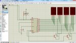
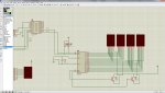
Having a go at this i2c! As per the diagram I am trying to get four segments to display different values. Is it something to do with applying a bit of lodgic to the multiplex outputs (11 & 14) ?

Thanks

Code:
; Game clock count down routine
; Read the BCD value and start the countdown.
; Read if countdown is continuous or stops with shot ckock.
; PICAXE 20M2
; SAA1064

; 0 = $3F
; 1 = $06
; 2 = $5B
; 3 = $4F
; 4 = $66
; 5 = $6D
; 6 = $7D
; 7 = $07
; 8 = $7F
; 9 = $6F
; A = $77
; B = $7C
; C = $39
; D = $5E
; E = $79
; F = $71


#picaxe 20m2

main:
	i2cslave $70, i2cslow, i2cbyte					' PICAXE is Master, send byte
	
	writei2c 0,(%01000111)							' write to location 0 and what to write.
	
	;writei2c 1,($06, $66, $4F, $7D)
	
	writei2c 1,($06)								' write "1" out MX1 pin 11
	
	writei2c 1,($66)
	
	writei2c 2,($4F)								' write "3" out MX2 pin 14

	writei2c 2,($7D)
	
	pause 300
	
	goto main
i2c.jpg
 
Last edited by a moderator:

SAborn

Senior Member
Here is some notes from a kit we done using this chip some years ago, see if it is of any help to you.

View attachment I2C 4 DIGIT LED DISPLAY MODULE_2_.pdf


Its been a long time since i done the circuit work for this driver but by memory (which might be wrong) i do belive that segment 1 and 3 are paired then 2 and 4 are paired together (and not 1 & 2 or 3 & 4 paired as you have them)
Also i did not use the transistors but that should not matter.

CExt ...has the cap wired wrong too in your diagram

NOTE- use [...] square brackets for code tags on the forum.
 
Last edited:

PaulRB

Senior Member
CExt ...has the cap wired wrong too in your diagram
I think that's OK. The cap should be wired between Cext and 0V, which it is. It just so happens ADR is also wired to 0V. I did the same with my project.

If you had multiple SAA1064 on the same i2c bus, you would have to wire their ADR pins differently, so the cap could not be connected to the ADR pin for those chips.

@ Jaden, can you describe the problem you're getting more precisely please?

One thing I did spot in your code: you are sending two bytes to address 1 and then 2 bytes to address 2. I think you need to send 1 byte each to addresses 1,2,3 and 4 for the 4 digits. A line of code above does this but it is commented out. What was the problem with that line of code?

Here's a link to my design so far, which also uses SAA1064 (currently working on PCB design with Fritzing).

Paul
 

SAborn

Senior Member
I think that's OK. The cap should be wired between Cext and 0V, which it is. It just so happens ADR is also wired to 0V. I did the same with my project.
NO! it is not ok, take a closer look, Cext is wired direct to ground, the cap is doing nothing.

Also the decoupling cap is missing from the circuit too.

On further inspection the segments are wired wrongly as i had commented above.

These are wonderfull displays when set up correctly, although they do become tricky to write into code for some projects.
 

Jaden

Senior Member
Hi all and thanks for your help so far. Sorry SAborn you are right. I redrew the circuit wrong and here is the correct diagram, my mistake.

Pin 1 ADR is taken to ground (Vee) and should give an address of $70 ?? Thanks for the code I now get H E L P but the 1st and 3rd display come on and the second and third black when they do and then vise versa. Do I now put in a #freq command to speed it up?

Having these two pins wrong has made my learining so far difficult, not I can get all four displays to work.

Sorry about the (code) I was told before, just picked the wrong way to do it.....

Now should I be sending a hex code? Will hopefully be easier when I have to start a countdown routine?

Now I get (with code) ramdon segments turning on and very briefly I get 1 2 9 0 .

Code:
; Game clock count down routine
; Read the BCD value and start the countdown.
; Read if countdown is continuous or stops with shot ckock.
; PICAXE 20M2
; SAA1064

; 0 = $3F
; 1 = $06
; 2 = $5B
; 3 = $4F
; 4 = $66
; 5 = $6D
; 6 = $7D
; 7 = $07
; 8 = $7F
; 9 = $6F
; A = $77
; B = $7C
; C = $39
; D = $5E
; E = $79
; F = $71


#picaxe 20m2

main:
	i2cslave $70, i2cslow, i2cbyte					' PICAXE is Master, send byte
	
	writei2c 0,(%01000111)							' write to location 0 and what to write.
	
	writei2c 1,($06, $5b, $6f, $3f)					'1 , 2, 9, 0
	;writei2c 0,(%00010111, %01110110, %01111001, %00111000, %01110011)
	
	wait 1
	
	goto main

One thing I did spot in your code: you are sending two bytes to address 1 and then 2 bytes to address 2. I think you need to send 1 byte each to addresses 1,2,3 and 4 for the 4 digits. A line of code above does this but it is commented out. What was the problem with that line of code?
Just playing with different ideas to get the four displays working, but the ADR pin problems is why I had issues.
 

Attachments

Jaden

Senior Member
Ok much betterer code!

Code:
main:
	i2cslave $70, i2cslow, i2cbyte					' PICAXE is Master, Address $70, send byte
								
	
	writei2c 0,(%00010111, $4F, $3F, $3F, $3F)			'display address, send 0 3 0 3 
				
	goto main
now get 1st & t3rf flash 3 0 and 2nd & 4th display blank, then 0 0 on display 2 & 4 while 1 & 2 blank. Need to get all on at once.
 

SAborn

Senior Member
What capacitor do you have on the Cext pin???? as this sets the MX frequency.
If you use the 2.7n cap as recommended then all should work, it is important to include the decoupling cap too.

Here is a program you can try, that should work for you, as it has on all the displays i have ever tested.

Code:
symbol d1 = b0	'digit 1
symbol d2 = b1	'digit 2
symbol d3 = b2	'digit 3
symbol d4 = b3	'digit 4
symbol digit = b4	'binary value of digit to be converted
symbol y = b5
symbol disp = %01110000	'Display i2c address
symbol dispcode = %01000111	'Display control byte - brightness etc

setfreq m4

i2cslave disp, i2cslow, i2cbyte 'display address

start:

gosub blank		'clear all digits to start

'Display the message "HELP" from right to left scroll

for y = 21 to 0 step -1
 	digit = y
 	pause 500
 	gosub message
 	d1 = d2:d2=d3:d3=d4
	d4 = digit
		
	writei2c (0,dispcode,d1,d2,d3,d4) 
		
next y

'brief pause to let it sink in, then blank all
	pause 1000
	d1=0:d2=0:d3=0:d4=0
	writei2c (0,dispcode,d1,d2,d3,d4) 
	
	
'display all digits counting from 0 to 9 pause and blank all
	
for y = 0 to 9
	digit = y
	gosub bcdto7seg
	d1 = digit:d2=d1:d3=d1:d4=d1	
	writei2c (0,dispcode,d1,d2,d3,d4) 
	pause 200
next y
	
	gosub blank

pause 500

'This lights up all decimal points - bit 7
for y = 1 to 30
	d1=$80:d2=d1:d3=d1:d4=d1
	writei2c (0,dispcode,d1,d2,d3,d4) 
	pause 50
	gosub blank
	pause 100
next y	
goto start

'This blanks all digits

blank:
	d1=0:d2=0:d3=0:d4=0
	writei2c (0,dispcode,d1,d2,d3,d4)
	return

'	
'Display the message "HELP" letters are in reverse order
'
message:
	lookup digit,($50,$79,$6f,$6f ,$1c,$7c,$40,$40,$73,$38,$79,$76,$40,0,$40,0,$3f,$38,$38,$79,$76 ),digit:return
'
'these are codes for numbers 0 to 9
'
bcdto7seg:
	lookup digit,($3f,$06,$5b,$4f,$66,$6d,$7d,$27,$7f,$6f),digit:return
 

Jaden

Senior Member
Thanks SAborn, I have a 2.7nF (2700pF) ceramic cap on the CEXT pin. With your code I get random segments! SO I will examin my diagram as it must have something wrong!
 

Jaden

Senior Member
As per my latest diagram the cap iscorrect. I am thinking that the VSM software may be an issue? I cannot see what is wrong with the circuit now. I may have to breadboard this one!

It does show HELP but it just flashes the letters and there is no solid display. On the last routine for the count from 0 to 9 the 4 digits are nearly all there but still randomly flash. mmmmmmmm
 

SAborn

Senior Member
What 7seg displays do you have?

Is this just being tested in software or do you actually have a hardware circuit setup.

It sounds like there is short circuits within the circuit causing the random numbers, if you have one of those 4 x 7 seg displays all in one (40 pin device) which is what i have used then there is some that are faulty internally, i have had about 3 out of 20 or so that gave strange random errors, and changing the display fixed the problem. (not a driver problem)

The other cause might be your power supply, what is this at present??? as the display uses a lot of juice with some numbers, and might be tripping out under load.
 

Jaden

Senior Member
So far this part is just software, PICAXE-VSM.

I have brought one of these http://www.gravitech.us/i2c47di.html . to use in one part of the project and have decided to do the same on some bigger kingbrights (about 12cm)I have on a remote panel to do the same program, but I have just realised that they are common cathode so I may have to rethink that part of the circuit.

So with the gravitech board it will be easy to breadboard the circuit and see if the VSM software is the issue.

Thanks for your great tutorial, it has been the easiest to follow so far, it is great to see how little code is needed to run on the i2c bus. So hopefully I can get back to my own program using bits of yours when I sought out this issue. I will report back hopefully tomorrow.

Cheers
 

hippy

Ex-Staff (retired)
You use ":" a bit in the code, what does this do?
That's a 'statement separator', allows two or more lines to be placed on a single line, eg

b0 = 0
b1 = 11
b2 = 2

Could be compacted into a single line by separating with colons (:) ...

b0 = 0 : b1 = 11 : b2 = 2

It's main use is to aid readability and to keep the length of source code shorter ...

b0 = "H" : Gosub SendB0 : Pause 1000
b0 = "i" : Gosub SendB0 : Pause 1000
b0 = "!" : Gosub SendB0 : Pause 1000

is arguably clearer and more quickly understood than ...

b0 = "H"
Gosub SendB0
Pause 1000
b0 = "i"
Gosub SendB0
Pause 1000
b0 = "!"
Gosub SendB0
Pause 1000
 

SAborn

Senior Member
That is just another way to write the code all on one line that would have been on seperate lines.

Example:-

This ........" d1 = d2:d2=d3:d3=d4"

Is the same as ...........

d1 = d2
d2 = d3
d3 = d4

Edit....... Hippy has quicker fingers than me.
 

Jaden

Senior Member
Well today is a good day. Always good when you get something new to work! I used SAborn's HELP example from his tutorial on my bread boarded gravitech type display and was able to get four stable and constant H E L P showing.

I would say that the VSM simulation is runnig at a slow speed and thus the digits are not all constant at once.

Thanks for the help and also mostly the lesson on i2c.

Cheers.
 
Top